


Making external connections Quatech Freedom USB Adapter User’s Manual
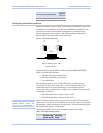
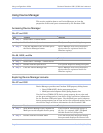
See Figure 39 on the following page for a typical null modem cable.
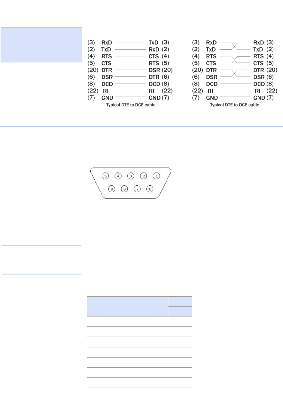
Figure 39 - Cabling requirements for RS-232C devices
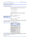
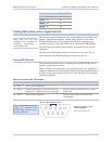
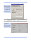
RS-422/485 serial connections
The Freedom USB-200/300 RS-422/485 adapters all come with standard
female DB-9 connectors. The figure below shows the pin designations.
Figure 40 - RS-422/485 DB-9 pin designations
Freedom USB-200/300 serial USB adapters provide four differential
communication signals (either RS-422 or RS-485) per channel.
Transmit Data (TxD) and Auxiliary Output (AuxOut) are the two
output signals. Receive Data (RxD) and Auxiliary Input (AuxIn) are
the two input signals. The adapters also provide a ground signal.
The AuxOut pair can carry the UART’s RTS signal. The AuxIn pair
can carry the UART’s CTS signal. Alternatively, the AuxOut pair can
be configured to internally loopback to the AuxIn pair, with the
UART’s RTS signal also looped back to its CTS signal. The following
table shows the RS-422/485 connector definitions.
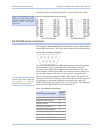
Table 4 - RS-422/485 DB-9 signal definitions
All ports
RS-422/485 signal description
DB-9
Auxiliary Output (AuxOut+) 1
Transmit Data (TxD+) 2
Signal Ground 3
Receive Data (RxD+) 4
Auxiliary Input (AuxIn+) 5
Auxiliary Output (AuxOut–) 6
Transmit Data (TxD–) 7
Receive Data (RxD–) 8
Note: Refer to Advanced
Options using Device Manager
for details on software-
selectable advanced options.
Figure 39 illustrates the RS-
232C pinouts for typical DTE-
to-DCE and DTE-to-
D
TE (null
modem) cables with 25-pin
connectors.
Page 30 Rev 2.02 (2/24/2004)