13
English
ALARMS
ON BATTERY
When the UPS is operating on the batteries, the On-Battery LED will illuminate
and the audible alarm will sound once every ten-seconds. The alarm will stop
once the UPS returns to the AC normal mode.
LOW BATTERY WARNING
The UPS will sound two beeps every five-seconds when the battery reserve
runs low. This condition will continue until AC returns or the UPS shuts down
from battery exhaustion.
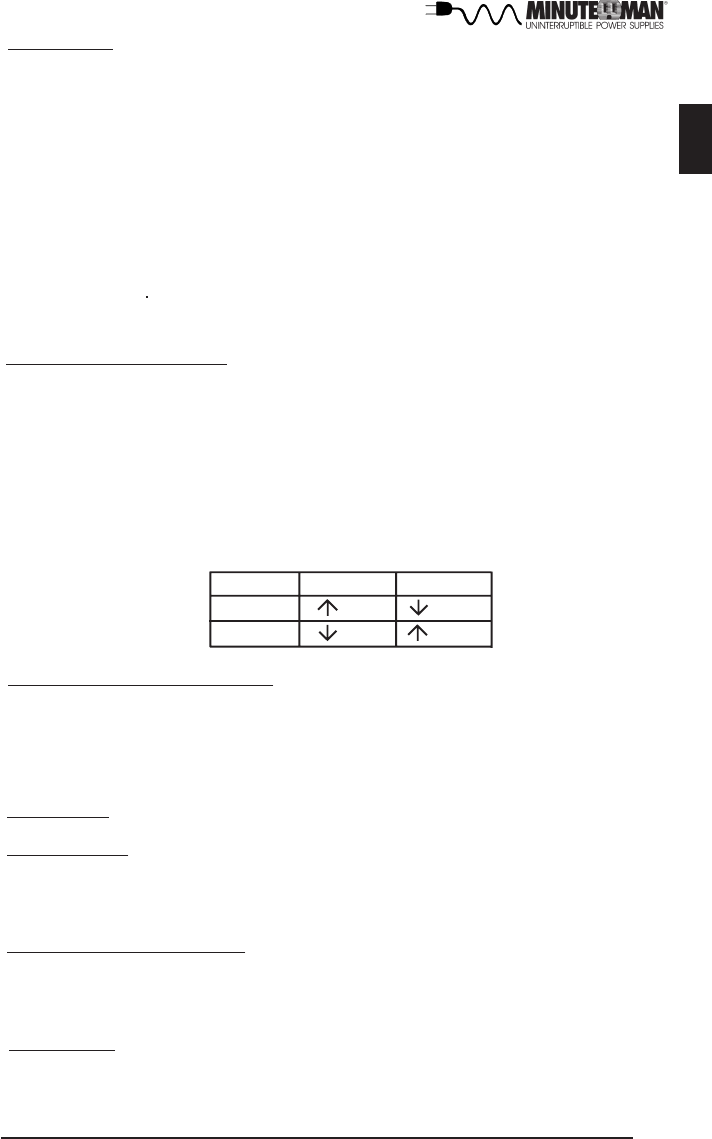
DIP SWITCH SETTINGS
The DIP Switch setting may be changed by the user to set the desired Inverter
(On-Battery) output voltage. The DIP Switch must be set to the desired Inverter
(On-Battery) output voltage and then the UPS must be turned off and restarted
to reconfigure the microprocessor and save the changes. The Inverter (On-
Battery) output voltage setting can be either 120VAC (default) or 127VAC. Chang-
ing the Inverter (On-Battery) output voltage to 127VAC, will also change the
Buck setpoint from 130VAC (default) to 137VAC.
Switch 1 2
120V (Off) (On)
127V (On) (Off)
SELF TEST
The self test feature is useful to verify the correct operation of the UPS and the
condition of the batteries. With the UPS in the AC normal mode, press and
hold the On/Off/Test Button for four beeps, then release the button. The UPS
will perform a ten-second self test. During the self test, the UPS will switch to
battery power and the On-Battery LED will illuminate and the audible alarm will
sound. The length of the test that is automatically performed every two weeks
is longer than the start-up or user invoked test. This test will run for approxi-
mately fifteen-seconds to measure the battery’s capability to provide an ac-
ceptable amount of runtime. If the UPS fails a self test, one of the LEDs will
remain illuminated indicating the type of problem. NOTE: The UPS will auto-
matically perform a self test on start-up and every two weeks.
UPS FAULT
When the UPS detects a hardware fault, the Fault LED will illuminate and the
UPS will sound a constant alarm. The fault condition, in some instances, may
be reset by turning the UPS off and then on.
Inverter (On-Battery)output voltage
LOAD SHEDDING FUNCTION
The output receptacles are electrically wired into two segments to support the
"Load Shedding Function". The user can control the two segments individually
or both at the same time. The Load Shedding Function is controllable by the
Power Monitoring Software or the SNMP card.


