


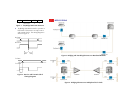
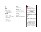

TERMINAL BLOCK
SCREW TERMINAL
RX
TX
GND
4-WIRE CABLE
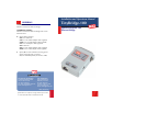
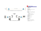
TinyBridge-100
WAN
LAN
100
PWR
LNG
FLC
FP
ON
100
FDX
AN
ON
FIL
Figure 7. Connecting the 4-wire WAN
Interface
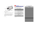
Connecting Power
1. Connect external power adapter to a mains
outlet
2. Plug in the external power adapter jack to
the TinyBridge-100. The PWR LED lights up
Note: While the TinyBridge-100 operates with any
regulated 5 VDC, 600 mA power supply, the CE
approval requires use of the power supply listed in
Ordering.
OPERATION
TinyBridge-100 operation is automatic. Table 2
shows how to diagnose the status of the
TinyBridge-100 from the LED indicators.
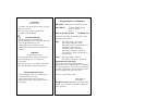
Table 2. LED Indicators
LED Color Description
PWR
Green ON – Power is connected
OFF – Power is disconnected
WAN
Yellow ON – Activity on WAN (includes idle)
OFF – No activity on WAN
Red
1
ON – Error condition on WAN
OFF – No error condition on WAN
LAN Green
OFF – No link integrity
ON – Link integrity
Yellow OFF – No activity on LAN
Blinking – Activity on LAN
100 Green ON – 100 Mbps LAN
OFF – 10 Mbps LAN
1
4-wire model
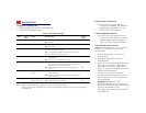
Table 3. DB-25 Pin Allocation
(V.24/RS-232)
Pin Name Type
1 SHIELD
2 TxD
Output
3 RxD Input
4 RTS Output
5 CTS Input
6 NC
7 GND
8 NC
9 NC
10 NC
11 NC
12 NC
13 NC
14 NC
15 TCLK Input
16 NC
17 RCLK Input
18 NC
19 NC
20 NC
21 NC
22
23 NC
24 NC
25 NC