


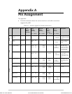


Appendix A Pin Assignment MBE Family Installation and Operation Manual
A-6
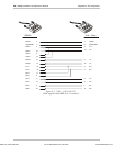
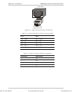
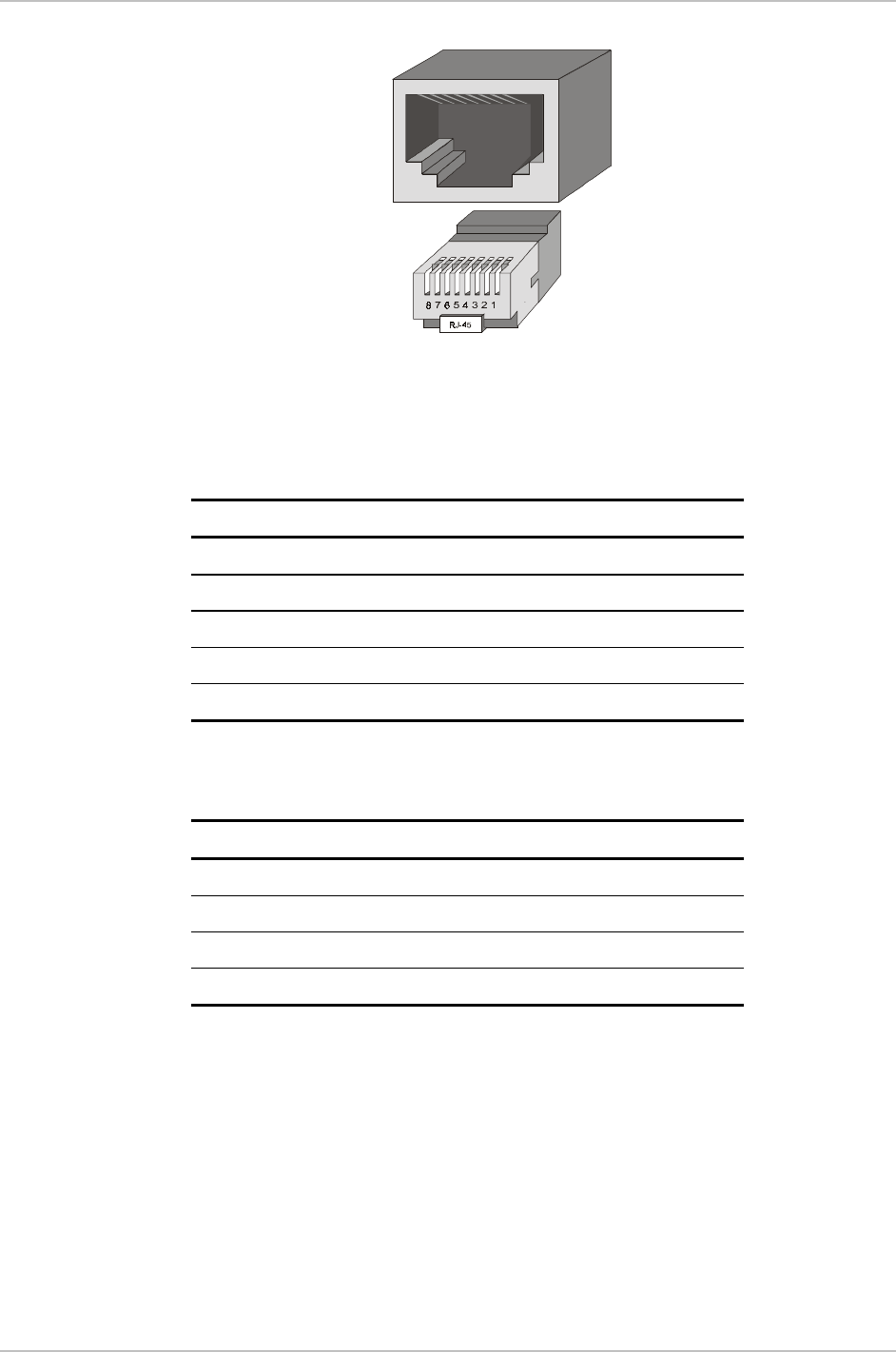
RJ-45 socket
Rx pair: pins 3 and 6
Tx pair: pins 1 and 2
1 2 3 4 5 6 7 8
Figure A-5. 10BaseT Connection (for UTP Ethernet)
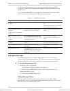
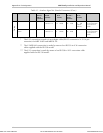
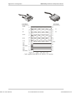
Table A-2. Control Cable RJ-45 to DB-9 Connection (DCE)
RJ-45 DB-9
Pin 4 GND Pin 5 GND
Pin 5 TX Pin 2 RX
Pin 6 RX Pin 3 TX
Pin 7 RTS Pin 8 CTS
Pin 8 CTS Pin 7 RTS
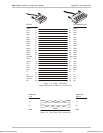
Table A-3. ISDN "S" Interface Cable Pin Assignments
Pin Number Signal Name
3 Tx+
4 Rx+
5 Rx–
6 Tx–
Order from: Cutter Networks
Ph:727-398-5252/Fax:727-397-9610
www.bestdatasource.com