


WEB1• 12
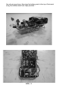
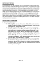
the motor is tightly held in place. I found that pulling the wire taut with my
needle nose pliers helped me snug it up into its proper position. Repeat
this procedure for the other motor using the other outline on the top of the
board as a guide.
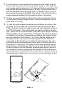
20. It’s time to solder the wires to the little pads at the end of the motor.
The motor should be held still by the hold-down wires you just installed so
it shouldn’t roll while you solder the power wires on. Cut 2 pieces of the
red/black twisted wire, each about 2 inches long. Strip back one end of
each wire about 1/16”. Now soldering the ends onto a motor is a little
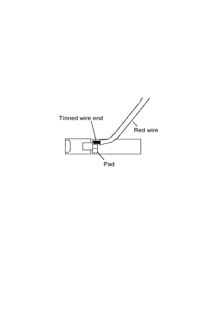
tricky. Once you’re sure that the motor is secured, tin a red wire end really
well so that you have a good amount of solder on it. Next, hold the tinned
end on the right side pad and heat it with your iron until the solder flows
onto the pad. It doesn’t take much heat. Be careful when heating the pads
up. The motors are a little sensitive to the heat and can’t be baked to
death like most other components. Solder the black wire to the other pad,
and then repeat this whole process for the other motor.
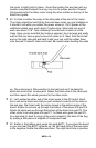
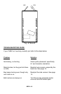
21. Let’s solder the other end of the motor wires to the PC board. Each
has a red and a black wire that you just soldered correctly to the motor in
the last step. We’ll start with the motor closest to the bottom edge of the
board. Solder its red wire up through the bottom of the board into pad P4.
Solder its black wire up through the bottom of the board into pad P3. The
other motor’s red wire goes into pad P1. Its black wire goes into pad P2.
As a last step it’s best to snug up the motor closest to the back of the bug
by putting a little piece of snipped off component lead
22. Solder in the battery pack wires into pads BAT1. If you place the board
so you can read the BAT1 rightside up, the left hand hole of the two holes
is the negative. Solder the black wire here. The right hand hole is positive;