


32185/32186/32192/32195/32196 Group
Starter Kit User’s Manual M3A-2154G52B
REJ10B0223-0140/Rev.1.40 Jan. 2007 Page 39 of 79
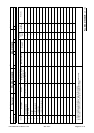
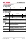
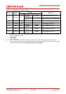
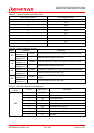
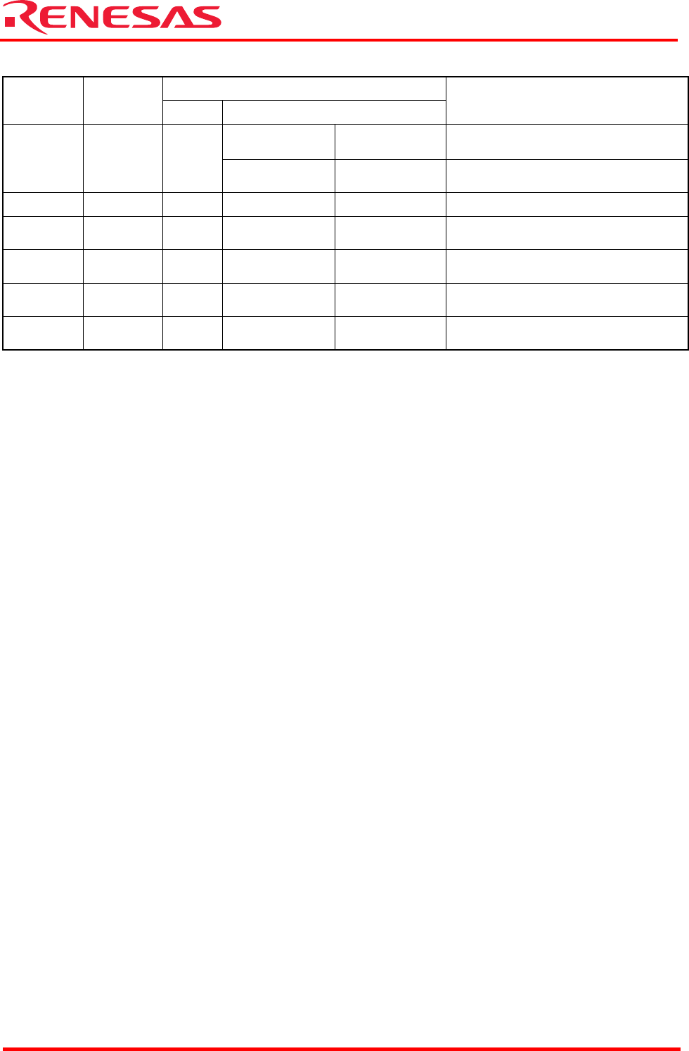
Table 2.1 Configuration of the Power Supply
Jumper
Connector
Power
Supply
Name Condition
Description
Shorted
between 1–2
Default Power supply from VCCE (CN2)
CN1 VCC-BUS J3
Shorted
between 2–3
Power supply from VCC-BUS (CN1)
CN2 VCCE — — — VCCE power supply
— VCCER J4
Shorted
between 1–2
Default
(Note1)
Power supply from VCCE
— AVCC0 J5
Shorted
between 1–2
Default Power supply from VCCE
— VREF0 J6
Shorted
between 1–2
Default Power supply from AVCC0
— VDDE J7
Shorted
between 1–2
Default Power supply from VCCE
Note1: Case of opened between 1-2, power supply from VCCE is stopped.
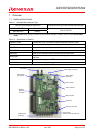
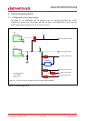
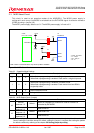
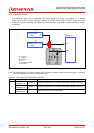
Case that 3.3 V power supply is inputted to VCCER by using 3.3 V generated circuit on board, the following items
should be prepared by the user.
- U3: regulator
- D1,D2: diode
- C4,C5: capacitor
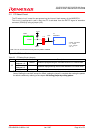
Note: The J3, J4, J5, J6 and J7 jumpers are shorted by pattern wiring on the reverse side of printed Circuit board.
Case of setting the condition except for default, setting the jumper is required after cutting the pattern for default
condition by referring to the chapter 3.8 Setting jumper by cutting pattern.