


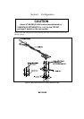
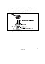
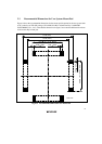
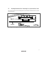
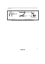
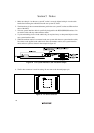

Figure 9 shows the system clock oscillator on the user system interface cable and the subclock input
specifications.
15
R2 270
R1 1 M
HCU04
HCU04
To E6000
emulator
OSC1 OSC2
System clock oscillator
Ω
Ω
0.8
Vcc
55
ns max. 55
ns max.
0.8
Vcc
0.3
Vcc
0
V
Vcc
Vcc: User System Vcc
(3.0 V to 5.0 V)
0.3
Vcc
Subclock input specifications
Figure 9 System Clock Oscillator and Subclock Input Specifications