


14
Section 4 Verifying Operation
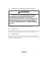
1. When using the H8/300L series E6000 emulator (HS388REPI60H), turn on the emulator
according to the procedures described in the H8/300L Series E6000 Emulator User's Manual
(HS388REPI60HE).
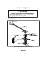
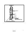
2. Verify the user system interface cable connections by accessing ports and checking the bus
states of the pins. If an error is detected, recheck the soldered IC socket and the location of
pin 1.
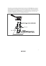
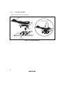
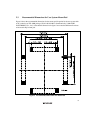
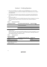
3. System Clock (OSC2, 1)
When the system clock is selected in the HDI Configuration Window and jumper P4 is set in the
user system interface cable, the system clocks in table 2 can be selected (see figures 9
and 10).
Table 2 Setting System Clocks
Configuration Window User System Interface Cable (P4) System Clock (∅)
2 MHz For the setting of P4, either pins 1-2
or 2-3 can be connected.
2 MHz
1-2 connected 5 MHz Target/2
2-3 connected Target clock/2
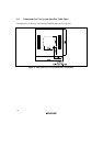
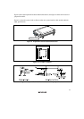
4. Subclock (DX2, 1)
When the switch is set on the expansion I/O board (Subclock selection) and jumper P5 is set on
the user system interface cable, subclocks in table 3 can be selected. Select target subclock in
the Configuration window (see figures 9 and 10).
Table 3 Setting Subclocks
Expansion I/O Board
(Subclock selection)
User System Interface Cable (P5)
Subclock (fW)
160 kHz 160 kHz
76.8 kHz
1-2 connected
76.8 kHz
The setting of the subclock
selection switch can be either
160 kHz or 76.8 kHz.
2-3 connected Target subclock