


Direct Drive LCD Design Guide
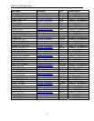
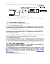
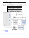
Figure 5 H8SX SDRAM in Cluster Mode
Note 1: To create the highest LCD Dot Clock frequency on the H8SX requires using cluster mode.
In this mode, EDACK is not generated and an equivalent signal must be generated. The above
circuit creates the necessary timing.
2.4
2.5
Driver Mode Configuration
The driver characteristics are configured with the following macros.
2.4.1 DOT_CLOCK_FREQUENCY_DATA
This macro configures the dot clock frequency during the data transfer portion of the LCD update cycle.
This value must be achievable by the configured BCLK_FREQUENCY and RAM configuration. This value
is checked against other system parameters and an error will be generated if the value is not achievable.
2.4.2 DOT_CLOCK_FREQUENCY_BLANK
This macro configures the dot clock frequency during the blanking portion of the LCD update cycle. This
value must be achievable by the configured PCLK_FREQUENCY as it generated by the TPU. This value
is checked against other system parameters and an error will be generated if the value is not achievable.
2.4.3 DESIRED_FRAME_RATE
This macro configures the initial selection of LCD frame rate. The frame rate can also be modified at
runtime via the LCDSetFrameRate API call. To achieve the desired frame rate, the vertical blanking time is
extended beyond the values configured in the LCD panel configuration. This value is checked against
other system parameters and an error will be generated if the value is not achievable.
2.4.4 MINIMUM_MCU_ACCESS_PCT
This macro configures the user’s minimum acceptable percentage of time that the MCU core has access
to the frame RAM (the MCU core only has access to the frame RAM during the vertical blanking time).
This value interacts with DESIRED_FRAME_RATE macro…higher access percentage is achievable at
lower frame rates (as the bus is less consumed with frame updates). This value is checked against other
system parameters and an error will be generated if the value is not achievable.
LCD Panel Configuration
The LCD Direct Driver is configured to operate with a given LCD panel by setting macro definitions.
These values are readily available in the data sheet for the selected panel.
2.5.1 DOT_INVERT
This macro is used to control whether the RGB data is latched on the rising or the falling edge of the dot
clock. If the macro is not defined, the data is latched on the rising edge, if it is defined, the data will be
latched on the falling edge. Note that when using the multiplexed EDACK and TPU modes, the EDACK
signal will also need to be inverted in hardware for falling edge operation (see
section on dot clock
hardware connections).
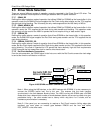
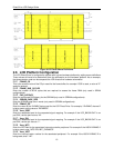
2.5.2 V_LINES_xx and H_DOT_xx
Refer to the following diagram for definition of these values.
9