


Section 4 Verifying Operation
1. When using the E6000 emulator for the H8S/2678 Series, H8S/2678R Series, H8S/2668 Series,
turn on the emulator according to the procedures described in the E6000 Series Emulator User's
Manual (HS2000EPI61HE).
2. Verify the user system interface cable connections by accessing the external memory and ports
to check the bus states of the pins with the MEMORY_FILL command (emulator command). If
an error is detected, recheck the soldered IC socket and the location of pin 1.
3. The emulator connected to this user system interface cable supports two kinds of clock sources
as the MCU clock: an emulator internal clock and an external clock on the user system. For
details, refer to the Emulator Supplementary Information (HS2678REPI61HE).
To use the emulator internal clock
Select the clock in the emulator station as the system clock (φ), by using the CLOCK
command (emulator command).
To use the external clock on the user system
Select target clock t or t2 with the CLOCK command (emulator command). Supply the
external clock from the user system to the emulator by inputting the external clock from the
EXTAL terminal on the cable head or connecting a crystal oscillator to the EXTAL and
XTAL terminals. For details, refer to section, Clock Pulse Generator, in the H8S/2678
Series, H8S/2678R Series, H8S/2668 Series Hardware Manual.
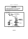
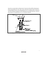
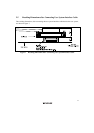
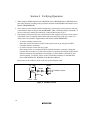
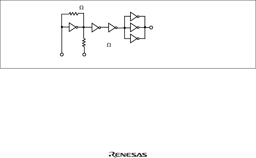
Figure 9 shows the oscillator circuit on the user system interface cable.
R2 270
R1 1 M
HCU04
HCU04
HCU04
To E6000 emulator
EXTAL XTAL
Figure 9 Oscillator Circuit
14