


26
Section 7 Restrictions
1. Deep-software standby mode
This emulator does not support deep-software standby mode.
Note that the emulator switches to the software standby mode even if the register setting to
select the deep-software standby mode is made.
2. Sleep-instruction exception processing
This emulator does not support the processing of sleep-instruction exceptions. Even if the
SLPIE bit of the standby control register (SBYCR) is set to 1, the execution of a sleep
instruction simply makes the emulator enter the low-power-consumption mode with no
exception processing for the sleep instruction.
3. User break controller (UBC)
The user break controller (UBC) is not available for this emulator.
Do not access the registers for the UBC, which are at addresses H’FFA00 to H’FFA34.
4. Serial communications interface (SCI5 and SCI6)
Since the port functions of pins PF5, PF7, P63, and P65 are not available when they are in use
for serial output, the states of these port pins cannot be read from the port registers. In this
situation, the input pull-up MOS and open-drain output functions are also not available.
5. Input-buffer control registers (PnICR)
In the actual device, setting a given bit of a PnICR to 0 disables the input buffer and fixes the
input signal to the high level; setting a given bit to 1 makes the corresponding pin available as
an input pin. On the emulator, however, input is enabled regardless of the settings of bits in the
ICR register.
When using any of the peripheral modules indicated below, however, ensure that the user
program has set the ICR bit for the corresponding pin to 1.
Relevant peripheral modules: SCI5, SCI6, ADC_Unit1, and ADC_Unit2
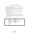
6. Port function control register D (PFCRD)
In this emulator, the port J and K functions cannot be selected by controlling the PCJKE bit in
the register PFCRD. A value read from PFCRD is always 0 and writing to PFCRD has no
effect. To select ports J and K, the position of the jumper in SW3 on HS1648ECH61H must be
altered (figure 19). In the product as shipped, the jumper is inserted to select ports D and E.
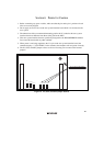
7. Port function control register 6 (PFCR6)
In this emulator, the ADTRG0#-B function cannot be selected by controlling the ADTRG0S
bit in the register PFCR6. To select ADTRG0#-B, the position of the jumper in SW2 on
HS1648ECH61H must be altered (figure 19). In the product as shipped, the jumper is inserted
to select ADTRG0-A.