Section 6 Points for Caution
Rev. 2.00 Sep. 08, 2008 Page 19 of 20
REJ10J1394-0200
Section 6 Points for Caution
1. Before connecting any parts or cables, make sure that the pins at the pin 1 position on both
sides are correctly aligned.
2. Do not apply excessive force to the user system interface board while it is connected to the
user system.
3. The dimensions of the recommended mounting pad for the IC socket for this user system
interface board are different from those of the pad for the MCU.
4. This user system interface board is specifically designed for the HS1650EPH60H emulator.
Do not use this board with any other emulator.
5. When power is not being supplied to the Vcc pin on the user system interface board, the
emulator displays ** VCC DOWN. In this situation, the emulator will not operate correctly.
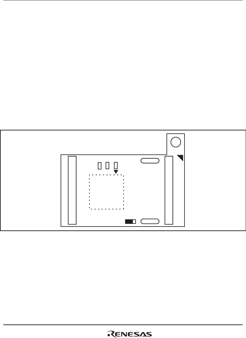
6. The P1 short connector is used for testing. Do not remove the inserted jumper pin.
P1
1
3
SW1
1
3
SW2
SW3
1
3
1
3
Figure 13 P1 Jumper Socket
7. The terminals of SW1 to SW3 are used to switch pins between port and CS-output functions.
Insert the jumper pins to select the desired function. When the pins are used for CS output, the
port functions are disabled. When the port functions of the pins are in use, the CS output
functions are disabled. At shipment, the port functions are enabled (i.e., the jumper pins are
inserted in “1”).


