


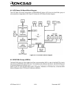

HTS Demo Kit V1.0 16/ 20 December 2007
Appendix A. Expansion Headers
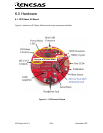
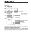
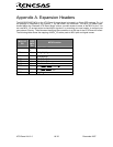
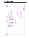
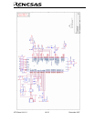
The M30260F8AGP MCU on the HTS Demo Kit target board is housed in a 48-pin QFP package. Pin 1 of
the package is identified by the number ‘1’ on the board’s top silkscreen. The MCU_I/O solder pads,
located below the “Renesas HTS Demo Board” sticker, provide access to some of the MCU’s pins. You
can use MCU_I/O as test points to check MCU signals or, by mounting your own header, to connect your
own external circuitry. The silkscreen identifying the connectors is at the top of the HTS Demo Kit board.
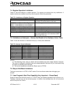
The following table shows the mapping of MCU_I/O solder pads to MCU pins and signal names.
MCU_I/O
Pin
48
QFP
MCU
Pin
MCU Function
Vcc 11,46,
47
V
cc
, V
REF
, AV
cc
AN4 40
P10
4
/AN
4
/
0
KI
AN5 39
P10
5
/AN
5
/
1
KI
TxD2 25 P7
0
/TxD
2
/ TA0
OUT
RxD2 24 P7
1
/RxD
2
/ TA0
IN
CLK2 23 P7
2
/CLK
2
/ TA1
OUT
/V
RTS2 22
P7
3
/
2
CTS /
2
RTS / TA1
IN
/ V
ADTrg 36
P1
5
/
3
INT /
TRG
AD / IDV
GND 9,44 V
ss
/AV
ss