


4
2.1.3 Installing IC Socket
CAUTION
Check the location of pin 1 before inserting.
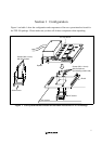
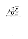
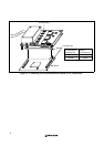
After checking the location of pin 1 on the user system interface board and pin 1 on the IC socket
connector, align the guide pins on the IC socket connector with the guide holes on the user system
interface board, and insert the IC socket connector into the IC socket (figure 2).
2.1.4 Fastening IC Socket Connector
CAUTION
1. Use the screwdriver provided for tightening screws.
2. The tightening torque must be 0.294 N•m or less.
If the applied torque cannot be accurately measured,
stop tightening when the force required to turn the screw
becomes significantly greater than that needed when first
tightening. If a screw is tightened too much, the screw
head may break or an IC socket contact error may be
caused by a crack in the IC socket solder.
3. If the emulator does not operate correctly, cracks might
have occurred in the solder. Check conduction with
a tester and re-solder the IC socket if necessary.
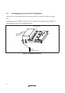
Fasten the user system interface board to the IC socket on the user system with four screws (M2
x
12
mm) provided.
Take special care, such as manually securing the IC socket soldered area, to prevent the soldered IC
socket from being damaged by twisting the components.