


( 45 / 48 )
Appendix B. Connection Diagrams
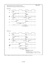
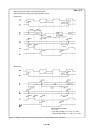
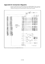
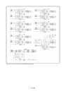
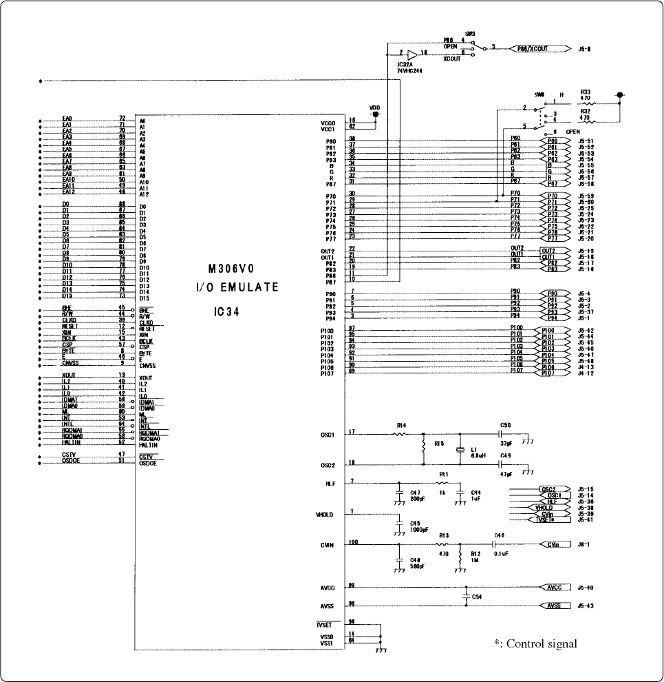
Figures B.1 and B.2 show the connection diagrams of the M306V0T-RPD-E. These connection
diagrams mainly show the interface section with a target system, and the circuits which are not
connected to the target system such as the emulator's control system are omitted.
Figure B.1 Connection diagram of the M306V0T-RPD-E (1/2)