


(3/4)
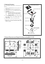
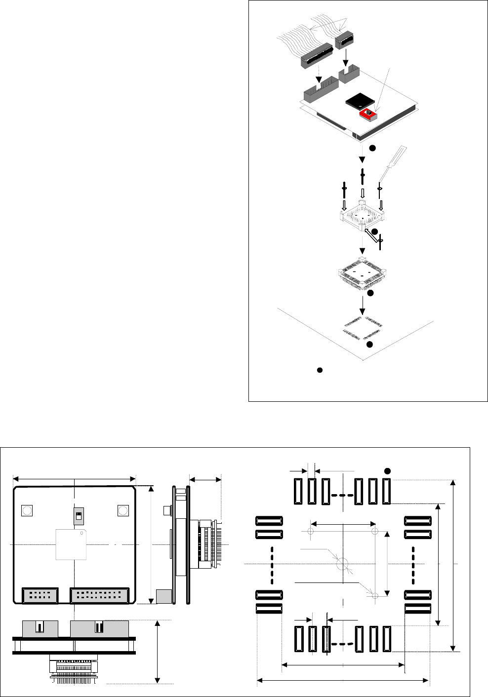
5. Attaching Procedure
How to attaching the M32171T-PTC is shown below. (see
Figure 3)
(1) Mount the NQPACK144SD on the foot pattern of the
target system
(2) Attach the YQPACK144SD to the NQPACK144SD.
(3) Secure the four corners of the YQPACK144SD with the
YQ-GUIDE’s.
(4) Set the clock selection switch.
EXT*
1
: The clock of pin XIN of the target board is
supplied to the MCU on the M32171T-PTC.
INT: The clock (10 MHz) on the M32171T-PTC is
supplied to the MCU.
(5) Connect the SDI MCU control interface cable and the SDI
trace interface cable of the emulator probe to the
M32171T-PTC.
(6) Attach the M32171T-PTC to the YQPACK144SD.
*1: When “EXT” is selected, take notice that the automatic
oscillation does not occur. Connect the output of the
oscillator to pin XIN.
Figure 3 Attaching procedure of the M32171T-PTC
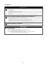
6. External Dimensions and Sample Foot Pattern of the M32171T-PTC
Figure 4 External dimensions and sample foot pattern of the M32171T-PTC
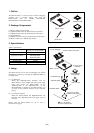
M32171T-PTC
YQPACK144SD
NQPACK144SD
YQ-GUIDE's (x4)
(2)
Interface cables of the probe
144-pin 0.5-mm-pitch
(144P6Q-A) foot pattern
: No. 1 pin position
Be sure to align the pins.
(1)
(3)
(4) Clock selection switch
(6)
(5)
3
4
.
0
I
C
1
0 . 25
J
2
6
6
.
0
J
1
S
W
1
I
N
T
M
3
2
1
7
0
T
-
P
T
C
A
R
E
V
.
A
M
A
D
E
I
N
J
A
P
A
N
C
L
K
-
S
E
L
E
X
T
19 . 0
23 . 0
0 . 5
7
.
0
7 . 0
2
3
.
0
1
9
.
0
(For SL)
6
8
.
0
16 . 0
: No. 1 pin
Hole for soldering NQ
f 3.2
3-f 1.0