


(5/6)
6. Selecting a Clock
With the M32192T2-PTC, it is possible to select a clock supply
to the MCU by the clock select switch (SW1). Select a clock
supply as shown below.
However, when used with the M32192T2-PTC, the clock
cannot be supplied from the user system.
(1) 20 MHz:
Supplies the clock (X1: 20 MHz) on the M32192T2-PTC
board to the MCU.
(2) SOCKET:
Supplies the clock to the MCU from the socket (X2) for
mounting an oscillator on the M32192T2-PTC board. By
mounting an oscillator to the X2 socket of the MCU, it is
possible to change the operating frequency.
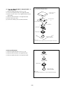
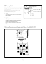
Figure 6.1 shows the connecting the X2 socket and the
MCU.
Connected to XOUT pin of MCU
R4
R10
C2
C1
R10 :
1MΩ
R4 :
510Ω
C1 :
27pF
C2 :
27pF
Mount an oscillator to X2 as
shown in the diagram printed on
the board.
Connected to XIN pin of MCU
X2 socket
Figure 6.1 Connection diagram of X2 socket
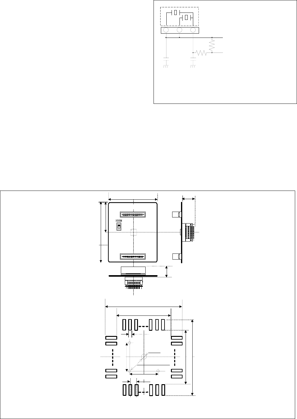
7. External Dimensions and a Sample Foot Pattern of the M32192T2-PTC
Unit: mm
14
0.25
105
SOCKET
M32192T2-PTC REV.A
MADE IN JAPAN
SW1
19
23
0.5
7
7
3-
φ
1.0
Hole for
soldering NQ
23
19
φ
3.2
for SL
85
16
●
: No.1 pin
20MHz
Figure 7.1 External dimensions and a sample foot pattern of the M32192T2-PTC