( 31 / 38 )
5.10 External Trigger Signal
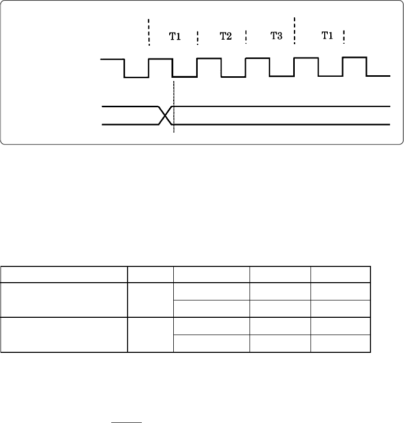
(1) External trigger signal input timing
The latch timing of the external trigger signal is shown in Figure 5.3.
Figure 5.3 Latch timing of external trigger signal
(2) External trigger signal input characteristics
Trigger breaks work according to the condition (leading edge/trailing edge) of signals input from
the external trace cable. The external trigger signals of the trace points and the external trigger
signals of the break points use the same signals. The input characteristics of the external trigger
signals are shown in Table 5.4 below. See the table before using external trigger signals.
Table 5.4 External trigger signal input characteristics
5.11 Other Precautions
With the M34502T-MCU if any of the following restrictions applies, it is necessary to evaluate the
system by an evaluation MCU (OTP version).
(1) The system which uses RESET output cannot be evaluated.
(2) The system which uses low-power detection function cannot be evaluated.
(3) The operation cannot be checked by a power-on reset.
(4) After resetting, it is not possible to change to the ceramic oscillation or CR oscillation by starting
up from the on-chip oscillator. After resetting, the system operates by the system clock of the
M34502T-MCU.
(5) As the operating voltage of the M34502T-MCU is 3 V or 5 V, the results of the A-D conversion
may differ from the theoretical values because of the difference with the voltage of the target
system.
(6) With the M34502T-MCU, it is not possible to evaluate the system which uses the multi
comparator function for 4580 Group.
System clock
XIN
External trigger signal
TRIG
Instruction Next Instruction
Item
H-level voltage
L-level voltage
VIH
VIL
Symbol
Voltage (V
CC)
2.0 V
4.5 V
2.0 V
4.5 V
Max.
-
-
0.5 V
1.35 V
Min.
1.5 V
3.15 V
-
-


