


(3/4)
5. Connection Procedure to the user system
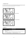
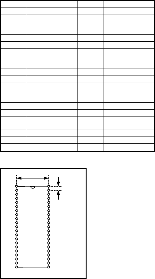
Connect the emulation probe to the connector on the upper panel of the M37549T-RLSS. Connect the M37549T-RLSS to the 42-pin
SDIP socket on the user system. Table 2 shows pin allocation of the M37549T-RLSS, and Figure 2 shows connector dimensions.
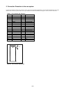
Table 2 CN1 connector pin allocation
Pin No Signal Pin No Signal
1 N.C 42 N.C
2 N.C 41 N.C
3 N.C 40 P13/AN3/KEY3
4 P14/AN4/KEY4 39 P12/AN2/CMP2
5 P15/AN5/KEY5 38 P11/AN1/CMP1
6 RESET 37 P10/AN0/CMP0
7 P16/AN6/KEY6 36 P31
8 P17/AN7/KEY7 35 P30
9 N.C 34 Reserved
10 N.C 33 Reserved
11 N.C 32 Reserved
12 P20/Xout/Xcout 31 Reserved
13 Vss 30 P07(LED7)/Srdy
14 P21/Xin/Xcin 29 P06(LED6)/Sclk
15 Vcc 28 P05(LED5)/TxD
16 CNVss 27 P04(LED4)/RxD
17 P00(LED0)/INT0 26 P03(LED3)/CAP0
18 P01(LED1)/INT1 25 P02(LED2)
19 N.C 24 N.C
20 N.C 23 N.C
21 Vss 22 N.C
* Do not connect signal to Reserved parts.
1 42
21 22
15.24
1.778
Figure 2 CN connector dimensions