


( 10 / 16 )
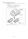
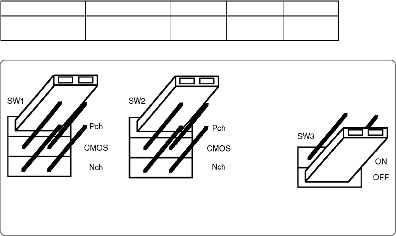
4.3 Setting the Jumper Switches
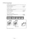
(1) Jumper switch SW1
Set the SW1 according to the output type of MCU's ports P20 - P23 (data buses D0-D3, No. 64-61
pins). For setting, see Table 4.1 and Figure 4.2.
• Ports P20 - P23: CMOS output ..............................................................................SW1: CMOS
• Ports P20 - P23: Pch output ...................................................................................SW1: Pch
• Ports P20 - P23: Nch output ..................................................................................SW1: Nch
(2) Jumper switch SW2
Set the SW2 according to the output type of MCU's ports P24 - P27 (data buses D4-D7, No. 60-57
pins). For setting, see Table 4.1 and Figure 4.2.
• Ports P24 - P27: CMOS output ..............................................................................SW2: CMOS
• Ports P24 - P27: Pch output ...................................................................................SW2: Pch
• Ports P24 - P27: Nch output ..................................................................................SW2: Nch
(3) Jumper switch SW3
How to set the SW3 is shown below.
•When No. 12 pin of the MCU is dedicated to pin XCIN .................................................................. SW3: ON
• When pin XCIN also serves as an I/O port (e.g. P41/XCIN) .....................................SW3: OFF
•When there is no pin XCIN ............................................................................................................................................. SW3: OFF
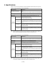
Table 4.1 Jumper switch settings
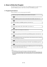
Figure 4.2 Jumper switch settings
Note: SW1 ....... Pch
SW2 ....... Pch
SW3 ....... OFF
MCU
M38B5XEXFP
M38B5XEXFS
Example
M38B59EFFP
M38B59EFFS
SW1 SW2 SW3
Pch
Pch OFF