


( 11 / 18 )
4.4 Setting Jumper Switches
(1) Jumper Switch SW1
Set the jumper switch SW1 according to the output format of the MCU ports P20 to P23. The examples
of switch settings are shown in Table 4.1 and Figure 4.3.
• When ports P20 to P23 are CMOS output ........................................................SW1: CMOS
• When ports P20 to P23 are Pch output..............................................................SW1: Pch
•When ports P20 to P23 are Nch output .............................................................SW1: Nch
(2) Jumper Switch SW2
Set the jumper switch SW2 according to the output format of the MCU ports P24 to P27. The examples
of switch settings are shown in Table 4.1 and Figure 4.3.
• When ports P24 to P27 are CMOS output ........................................................SW2: CMOS
• When ports P24 to P27 are Pch output..............................................................SW2: Pch
•When ports P24 to P27 are Nch output .............................................................SW2: Nch
(3) Jumper Switch SW3
Set the jumper switch SW3 according to the specification of the sub-clock XCIN pin. The examples
of switch settings are shown in Table 4.1 and Figure 4.3.
• When XCIN pin is dedicated pin for XCIN ..........................................................SW3: ON
• When XCIN pin is used also as a general I/O port (e.g. P80/XCIN) ....................SW3: OFF
•When there is no XCIN pin ................................................................................SW3: OFF
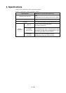
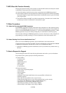
Table 4.1 Jumper switch settings of M38B79FFFP
MCU
M38B79FFFP
SW1
Pch
SW2
Pch
SW3
OFF
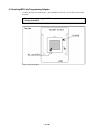
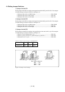
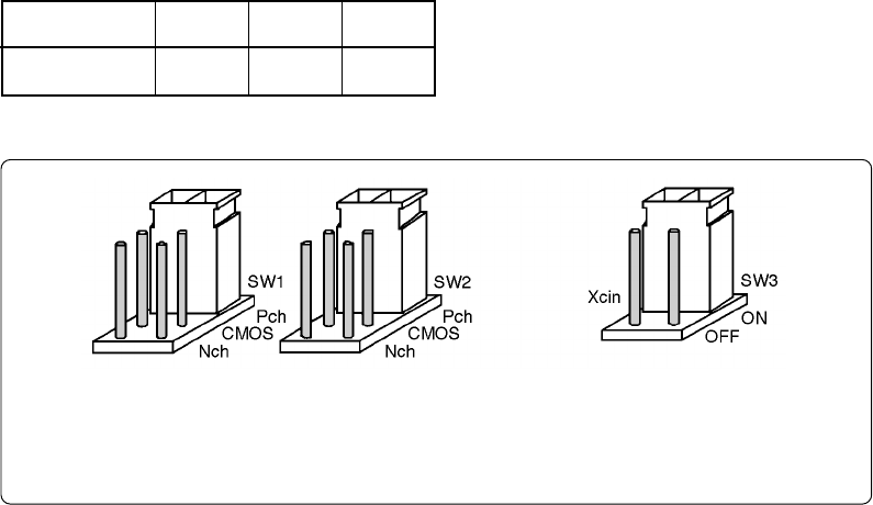
Figure 4.3 Jumper switch settings
Note: Switch settings for
SW1 ....... Pch
SW2 ....... Pch
SW3 ....... ON