


5
Section 3 User Interface Specifications
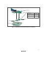
This user system interface board has the function that masks the chip select signals (CS0 and
CS1), bus request signal (BREQ), and wait input signal (WAIT) depending on the setting of a
switch.
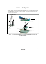
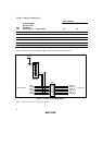
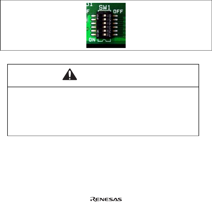
To use the mask function, set the switch (SW1) on the user system interface board (figure 2),
according to table 3, and mask pins.
Note: When the emulation memory function is used, the output of the chip select signals to the
user system is controlled. Be sure to mask the chip select signals (CS0 and CS1) that
correspond to the address area to which the emulation memory has been allocated.
Figure 2 Switch for Masking Signals
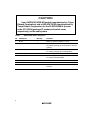
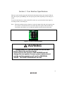
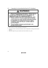
WARNING
Always switch OFF the user system and the emulator
product before the switches are set.
Failure to do so will result in a FIRE HAZARD and will
damage the user system, the user system interface board,
and the emulator product or will result in PERSONAL
INJURY. The USER PROGRAM will be LOST.