


(3/4)
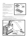
4 Connection with a User System
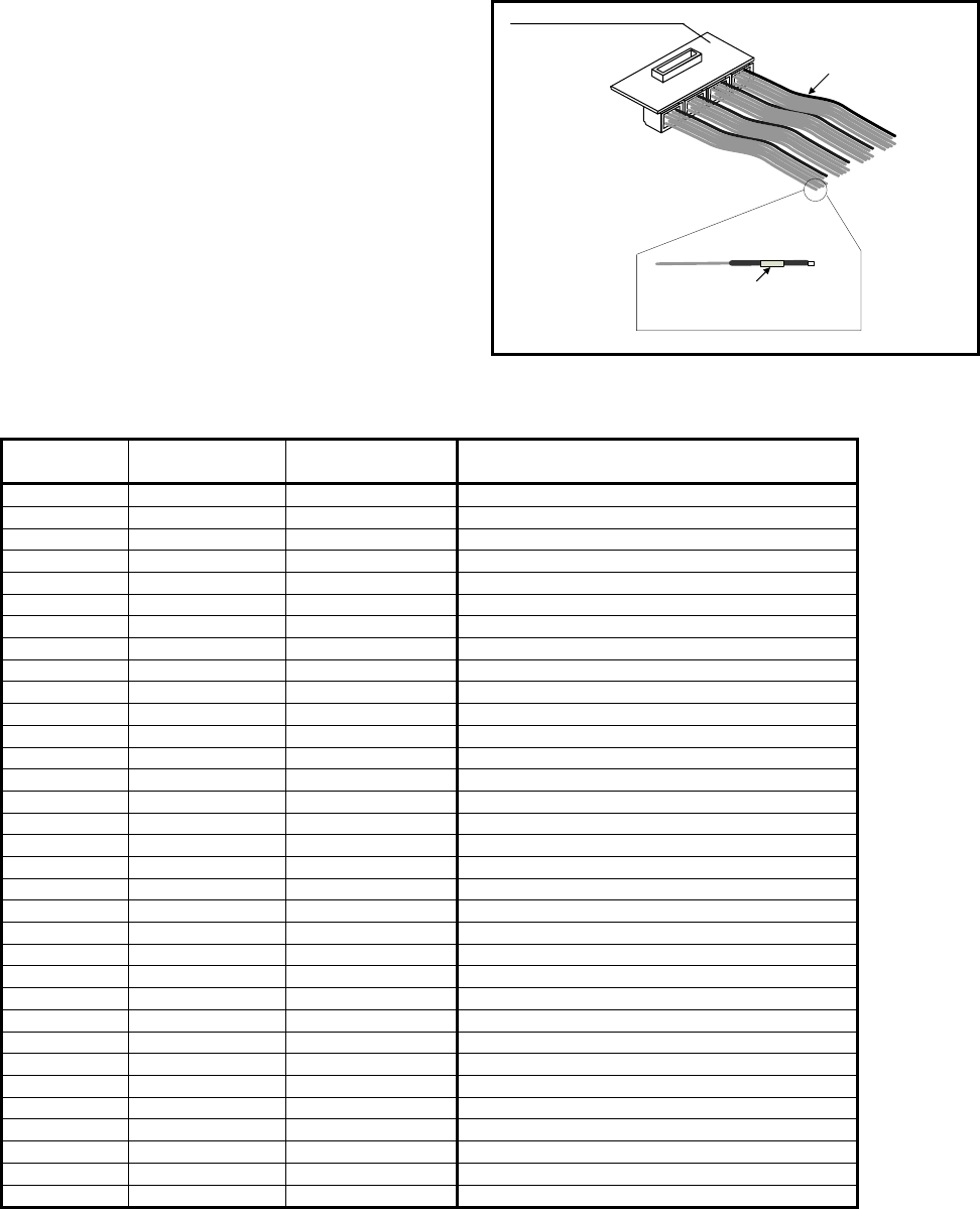
(See Figure 3)
(1) GND connection
The black wire connected to the R0E001000EXTT0 board
acts as a GND terminal. This wire must be connected to GND
of the user system.
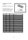
(2) Trigger-signal correspondence table
Input and output attributes for trigger signals are specifiable
through settings in the emulator debugger. Table 1 shows the
correspondence between the [Trigger] section ([External
trigger cable]) on the [System] page of the [Configuration
Properties] dialog box of the emulator debugger and
identification numbers for the user-system connection sockets.
Wires:
Black (GND) and gray (signal)
Identification number on the sticker
for each user-system connection socket
R0E001000EXTT0
Figure 3 Connection with a User System
Table 1 Trigger-Signal Correspondence Table
Trigger Signal
Name
Input/Output R0E001000EXTT0
Connector Number
Identification Number for the User-System
Connection Socket
CLK I CN3-2 CLK
EXT0 I CN4-10 0
EXT1 I CN4-9 1
EXT2 I CN4-8 2
EXT3 I CN4-7 3
EXT4 I CN4-6 4
EXT5 I CN4-5 5
EXT6 I CN4-4 6
EXT7 I CN4-3 7
EXT8 I CN3-10 8
EXT9 I CN3-9 9
EXT10 I CN3-8 10
EXT11 I CN3-7 11
EXT12 I CN3-6 12
EXT13 I CN3-5 13
EXT14 I CN3-4 14
EXT15 I CN3-3 15
EXT16 I/O CN6-10 16
EXT17 I/O CN6-9 17
EXT18 I/O CN6-8 18
EXT19 I/O CN6-7 19
EXT20 I/O CN6-6 20
EXT21 I/O CN6-5 21
EXT22 I/O CN6-4 22
EXT23 I/O CN6-3 23
EXT24 I/O CN5-10 24
EXT25 I/O CN5-9 25
EXT26 I/O CN5-8 26
EXT27 I/O CN5-7 27
EXT28 I/O CN5-6 28
EXT29 I/O CN5-5 29
EXT30 I/O CN5-4 30
EXT31 I/O CN5-3 31