


(3/4)
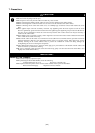
5. Connection Procedure (See Figure 3)
The procedure for connecting the R0E436640CFG20 is shown
below.
(1) Mount the IC socket on the user system.
(2) Connect the R0E436640CPE00 and R0E436640CIF00.
(3) Connect the R0E436640CFG20 and IC socket.
Fasten the IC socket to the socket cover with the four
screws (M2 x 12 mm) provided. Each screw should be
tightened a little at a time, alternating between screws on
opposing corners. Take special care, such as manually
securing the IC socket soldered area, to prevent the
soldered IC socket from being damaged by overtightening
the screws or twisting the components.
● When connecting the IC socket and socket cover, use
a Phillips-type screwdriver whose head matches the
screw head.
● If the applied torque cannot be accurately measured,
stop tightening when the force required to turn the
screw becomes significantly greater than that needed
when first tightening (The tightening torque must be
0.098 N•m or less). If a screw is tightened too much,
the screw head may break or an IC socket contact
error may be caused by a crack in the IC socket
solder.
● If the emulator does not operate correctly, cracks
might have occurred in the solder. Check conduction
with a tester and re-solder the IC socket if necessary.
(1)
(2)
(4)
(3)
64-pin 0.8mm pitch
foot pattern
(PRQP0064GB-A)
IC socket *
R0E436640CIF00
R0E436640CFG20
R0E436640CPE00
Screws (M2×12mm) *
Flat washers *
Figure 3 Connection procedure of the R0E436640CFG20
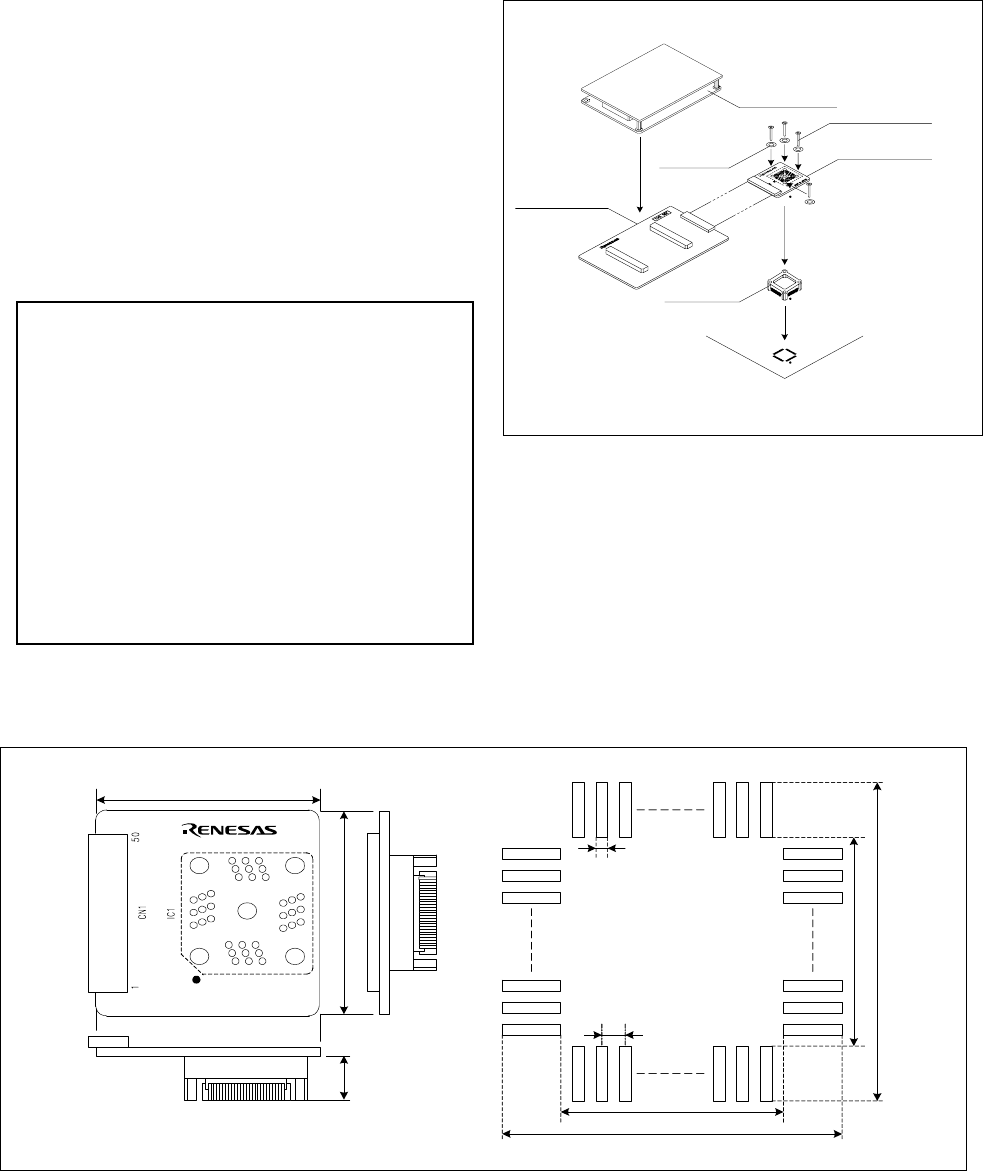
6. External Dimensions and a Recommended Foot Pattern (See Figure 4)
Note that the dimensions of the recommended foot pattern in Figure 4 are somewhat different from those of the actual foot pattern.
50.0
14.0 44.0
0.45±0.05
0.80±0.05
13.2(max14.80)
mn20.80
13.2(max14.80)
mn20.80
Unit: mm
R0E436640CFG20 REV.A
MADE IN JAPAN
Figure 4 External dimensions and a recommended foot pattern of the R0E436640CFG20