


Chapter 4.User Circuitry
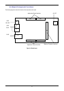
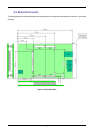
4.1.Fitting the Target RSK to the RSK application board
The board is supplied with 2x 24 way sockets, 2x 26 way sockets and 1 x 50 way socket.
These should be soldered on the underside of the host RSK in JA1, JA2, JA5, JA6 and JA3 positions.
The RSK should be plugged into the equivalent connectors on the RSK LCD application board.
A separate application note is available to explain how to configure the host RSK to enable it to connect to this
application board.
The board is designed to be 5V I/O tolerant. Therefore this board can be connected to an RSK with 5V I/O.
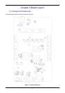
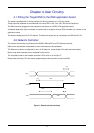
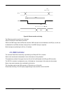
4.2.Network Controller
The network functionality is provided by the SMCS LAN9118-MT non-PCI Ethernet controller.
Refer to the manufacturer’s datasheet for more information on this peripheral.
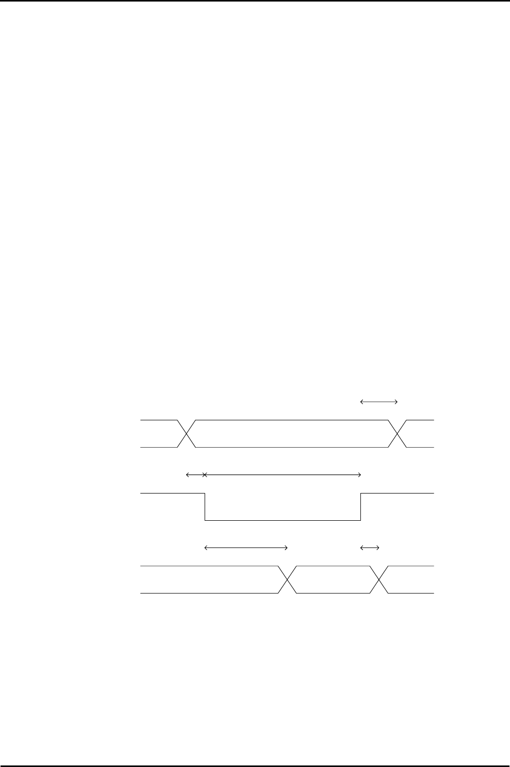
The Ethernet controller is configured to use a 16 bit data bus. It uses single 16 bit read and write strobes.
Byte or long word accesses are not available for this device.
The chip select used for the network controller is CS1 which is on JA3 pin 27.
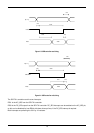
Please note the timing. This will require programming the bus controller for the Host RSK.
A[7:1]
CSn,RDn
Data
35ns
0ns
0ns
40ns
5ns
Valid
Figure 4-1: Ethernet controller read timing
8