


6
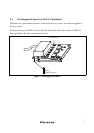
2.1.2 Fastening IC Socket Connector
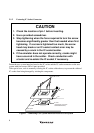
CAUTION
1. Check the location of pin 1 before inserting.
2. Use a provided screwdriver.
3. Stop tightening when the force required to turn the screw
becomes significantly greater than that needed when first
tightening. If a screw is tightened too much, the screw
head may break or an IC socket contact error may be
caused by a crack in the IC socket solder.
4. If the emulator does not operate correctly, cracks might
have occurred in the solder. Check conduction with
a tester and re-solder the IC socket if necessary.
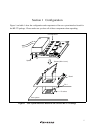
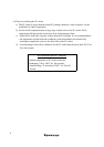
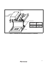
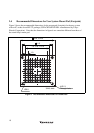
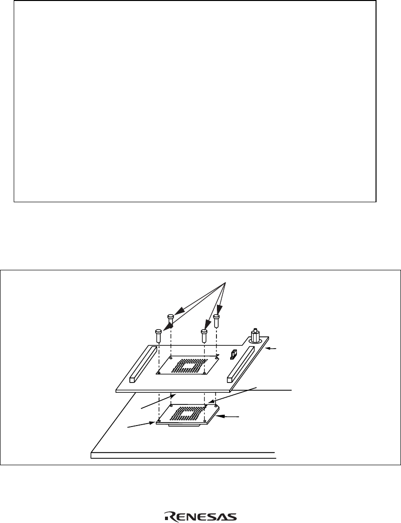
Fasten the user system interface board to the IC socket and the IC socket connector on the user
system with four screws (M2
x
8 mm) provided.
Take special care, such as manually securing the IC socket soldered area, to prevent the soldered
IC socket from being damaged by twisting the components.
IC socket
(Tokyo Eletech Corporation
CSPACK256Z2021H01)
Guide hole
Pin 1
Guide pin
Screws (M2 x 8 mm)
Board
User system
Figure 2 Connecting User System Interface Board to User System