7
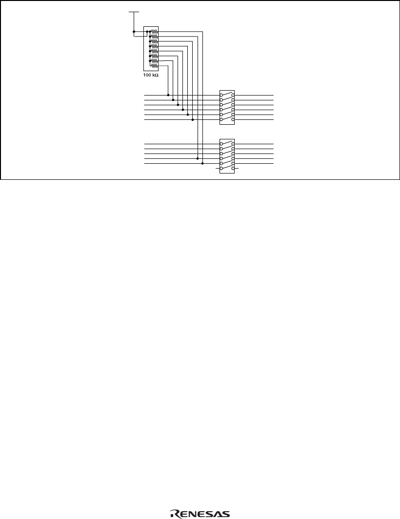
Figure 3 shows a circuit for masking signals on the user system interface board.
UVCC
PB7
PB8
PA 17
PE5
PA 10
PA 7
PA 1
PE6
PA 6
PA 11
PA 0
SW1
SW2
User system Emulator
PB7_C
PB8_C
PA17_C
PE5_C
PA10_C
PA7_C
PA1_C
PE6_C
PA6_C
PA11_C
PA0_C
Figure 3 Circuit for Masking Signals
Note: The UVcc is the Vcc in the user system.


