


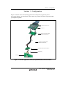
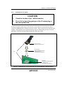
Section 3 Connection Procedures
Rev. 1.00 Nov. 18, 2008 Page 6 of 18
REJ10J1937-0100
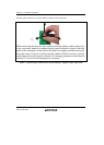
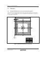
3.1.1 Installing the IC Socket
Solder the IC socket (BSSOCKET272Z2021RE21N) to the user system.
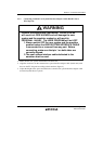
CAUTION
1. Gently apply solder paste to the BGA pads of the user
system. Be careful to keep the thickness of the solder
within 100 to 150 μm. Too much solder will cause
short-circuiting of the pins.
2. A strip of protective (polyimide) tape is stuck to the
surface of the IC socket which is to be connected to the IC
socket plug. This prevents the adhesion of scattered
(dispersed) flux in reflow for the IC socket. Leave this
protective tape in place until solder reflow has been
completed.
3. Since components that occupy large volumes close to the
area for mounting of the IC socket will prevent the
convective flow of heat during reflow, ensure that such
components are not present when the socket is mounted.
4. Do not dip the IC socket in flux or otherwise wash it.
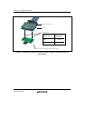
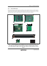
3.1.2 Assembling the User System Interface Cable
CAUTION
Check the location of pin 1 and the connector number before
insertion.
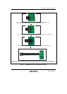
Connecting the user system interface cable
Connect the common user-system interface adaptor cable (board unit) for the user-system
interface converter board via the common user-system interface cable (cable unit).