


7
N.C.
N.C.
MPMD (GND)
TCK
N.C.
/AUDSYNC
N.C.
N.C.
AU DATA0
AU DATA1
UVCC_AUD
N.C.
N.C.
TMS
/UCON (GND)
N.C.
AUDCK
UVCC
N.C.
N.C.
/RESETP
/RESETA
TDI
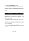
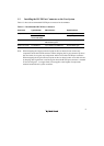
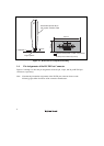
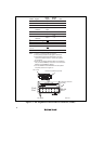
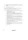
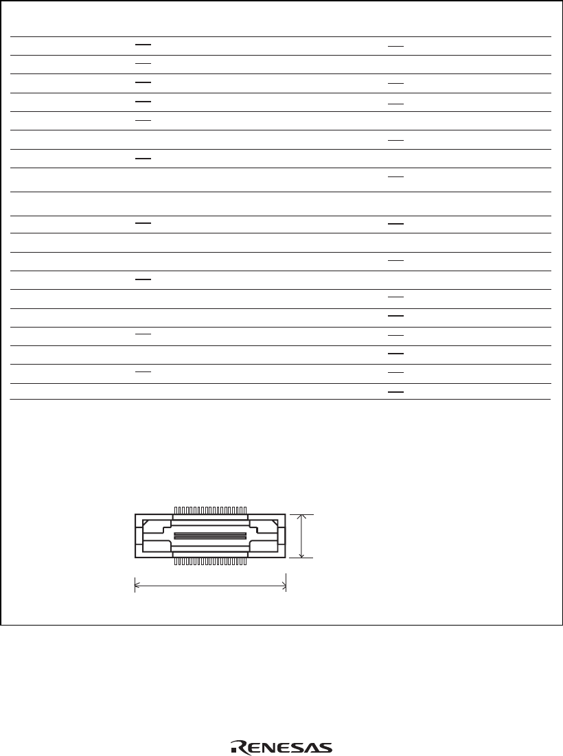
H-UDI port connector (top view)
Unit: mm
TDO
K13
K14
J17
K15
M15
Output
Output
Input/
Output
Output
Output
Output
Output
Output
Output
Output
Output
Input
Input
Input
Input
N13
D15
D12
1
2
3
4
5
6
7
8
9
10
11
12
13
14
15
16
17
18
20
21
22
23
24
25
26
27
28
29
30
31
32
33
34
35
36
37
N.C.
L13
M16
L14
L15
M13
M14
N.C.
/TRST
/ASEBRK/
BRKACK
N.C.
AU DATA3
N.C.
AU DATA2
N.C.
N.C.
N.C.
N.C.
N.C.
N.C.
N.C.
19
38
137
38 2
6.91
25.4
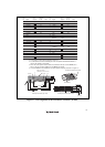
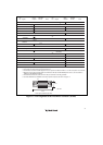
Pin
No.
Signal
Input/
Output
Note
Pin
No.
Signal
Input/
Output
Note
*1
*1
SH7362
Pin No.
SH7362
Pin No.
*4
*3
*2
*2
*2
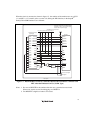
Notes:
1. Input to or output from the user system.
2. The symbol (#) means that the signal is active-low.
3. The emulator monitors the GND signal of the user system and detects whether or not the user system is connected.
4.
When the user system interface cable is connected to this pin and the MPMD pin is set to 0, do not connect to
GND but to the MPMD pin directly.
5. The GND bus lead at the center of the H-UDI port connector must be grounded.
6. Connect /RESETP and /RESETA to the user system if required, as shown in figure 1.7.
User reset
*2
Figure 1.4 Pin Assignments of the H-UDI Port Connector (38 Pins)