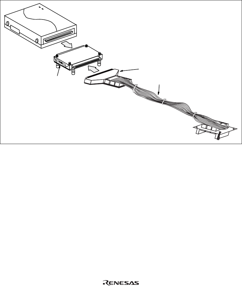
2. [1] After making sure the direction of the expansion board connector labeled E6000
EMULATOR is correct, firmly insert the expansion board connector into the emulator
station connector labeled USER INTERFACE ([1] in figure 2).
[2] Connect the expansion board labeled USER INTERFACE CABLE and the user system
interface cable body.
6
0
0
0
US
ER
I
N
TER
F
A
C
E
CA
B
L
E
E
6
0
00
EM
ULA
T
O
R
E6000
[2]
160kHz
Emulator station
Expansion board
[1]
Subclock selection
E
Cable body connector
User system interface cable
Figure 2 Connecting User System Interface Cable to Expansion Board
4


