


14
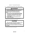
Section 4 Verifying Operation
1. When using the H8/300L series E6000 emulator (HS3L08EPI60H), turn on the emulator
according to the procedures described in the H8/300L Series E6000 Emulator User's Manual
(HS3008EPI60HE).
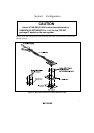
2. Verify the user system interface cable connections by accessing ports and checking the bus
states of the pins. If an error is detected, recheck the soldered IC socket and the location of pin
1.
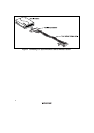
3. The emulator connected to this user system interface cable supports two kinds of clock sources:
an emulator internal clock and an external clock on the user system, for the MCU clock and
subclock. For details, refer to the H8/300L Series E6000 Emulator User's Manual
(HS3008EPI60HE).
To use the emulator internal clock
Select the clock in the emulator station as the system clock (φ) and the subclock
(φw), by using the CLOCK command (emulator command).
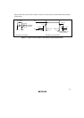
To use the external clock on the user system as the system clock
Select external clock t2 with the CLOCK command (emulator command). Supply the
external clock from the user system to the emulator by inputting the external clock from the
OSC1 terminal on the cable head or connecting a crystal oscillator to the OSC1 and OSC2
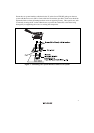
terminals. When a crystal oscillator is inserted into the OSC1 and OSC2 terminals for the
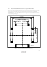
system clock, the clock is generated by the oscillator circuits shown in figure 9. To input an
external clock from the OSC1 terminal, input clock pulses satisfying the specifications
described in the MCU hardware manual. The system clock (φ) frequency is half of the
external clock frequency. For details, refer to section 4, Clock Pulse Generator in the
H8/3637 Series Hardware Manual.
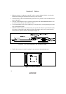
To use the external clock on the user system as the subclock
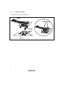
Select target clock (sub t) with the CLOCK command (emulator command). Supply the
external clock from the user system to the emulator. To input an external subclock from the
user system, input clock pulses satisfying the specifications shown in figure 9 into the X1
terminal. The oscillator circuits on the user system interface cable cannot generate external
subclock pulses by using the crystal oscillator connected to the user system.