


6
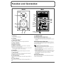
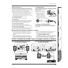
Function and Connection
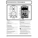
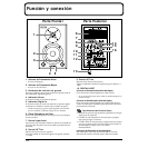
fig.03.e
1. HF Driver
* Do not touch the diaphragm.
2. LF Driver
* Do not touch the speaker cone.
3. Bass-reflex Ducts
These are conduits for rich, bass-range reproduction.
4. Power Indicator
Lights when power is on.
5. Digital In Indicator
This lights up when output is received from a connected
digital device or during standby.
* When the connected digital-signal output device is not powered
up, the Digital In indicator does not light up.
6. Heat Sink
This is a heat-radiating plate that dissipates excess heat.
7. Level Control
This adjusts the input level. Turning the control clockwise
increases the sound from the speakers.
8. HF Trim Control
This adjusts the sound quality of the treble range (10 kHz, +/
-3 dB).
9. LF Trim Control
This adjusts the sound quality of the bass range (80 Hz, +/-3
dB).
10. DIGITAL INPUT
Coaxial Input Connector (Digital Input)
This is the digital input connector for coaxial cable.
* It cannot be used for input of analog audio signals (no sound is
produced).
Optical Input Connector (Digital Input)
This is the digital input connector for optic-fiber cable. Use
commercially available optical cable for audio equipment to
make the connection.
Optical-connector Protective Cap
• After removing the protective cap, put in a safe place so
that it doesn’t get lost.
• When not using the optical connector, attach the cap to
keep the connector safe.
• When using the optical connector, be sure that the cap you
removed is placed out of the reach of children. If a child
has accidentally swallowed a cap, see a doctor
immediately.
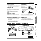
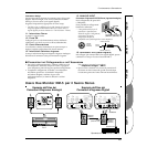
Digital Input Select Switch
This switch selects Optical or Coaxial. Select the connector
used for the input signal.
Front
1
6
7
8
9
10
11
12
13
14
15
16
2
3
45
Rear