


INSTALLATION
6
CRYSTALVIEW DVI FIBER INSTALLATION AND OPERATIONS MANUAL
Installation
Please refer to the safety section first before proceeding with any installation
or configuration of the CrystalView DVI Fiber.
When installing the CrystalView DVI Fiber, locate the transmitter as close as
possible to the CPU or switch. Keep the cables as short as possible but still
give some freedom of movement. You can mount the CrystalView DVI Fiber
in a CPU rack with the optional rack mount kit. When mounting the units in a
rack, follow the instructions in Appendix D and Appendix E. Provide adequate
air circulation to assure that the maximum operating temperature is not
exceeded.
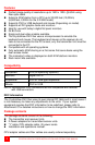
For dual video models, connect a second DVI monitor and additional fiber
cable from the transmitter to the receiver. The bottom Fiber connector on the
Dual video models carries Video 1 and data, top fiber connector carries only
Video 2.
Wherever the transmitter and receiver units are located, they should be on a
secure surface and free from obstructions and objects that may cause
damage to the units.
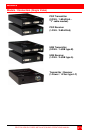
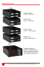
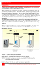
Figure 1. Typical cabling configurations
(See Figure 1 for the connector locations for your model)
NOTE: Using the local access model, a second KVM station can be
connected to the transmitter.
Refer to Figure 1 for the set-up for your system application.
LOCAL KVM REMOTE KVM
ACCESS ACCESS
TRANSMITTER RECEIVER
Fiber cable
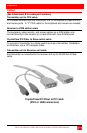
“Y” PS/2
Cable