


24-Port Gigabit Ethernet Switch RGS-1024 User Manual
-11-
Chapter 3. Identifying External Components
This Chapter describes the front panel, rear panel and LED
indicators of the Switch.
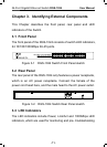
3.1 Front Panel
The front panel of the RGS-1024 consists of switch LED indicators,
24 10/100/1000Mbps RJ-45 ports.
Figure 3-1 RGS-1024 Switch Front Panel sketch
3.2 Rear Panel
The rear panel of the RGS-1024 only features a power receptacle,
which is an AC power receptacle. Connect the female of the
power cord head here, and the male head to the AC power outlet.
Figure 3-2 RGS-1024 Switch Rear Panel sketch
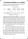
3.3 LED Indicators
The LED indicators include Power, Link/Act and 1000Mbps LED
indicators, which are used for monitoring and pre- troubleshooting