


14
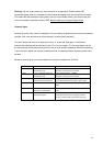
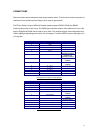
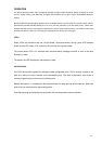
Pin Number Designation WRT Modem Notes
1 DCD
Optional not
normally needed
2 RX (data)
RS232 input
data to modem
3 TX(data)
RS232 output
data from
modem
4 RTS
Optional not
normally needed
5 GND
Ground
6 B RX(-)
RS485/RS422
7 A RX(+)
"
8 +Vs
Supply 7.5 to
15V dc
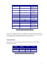
9 N/C
10 GND
Ground
11 Z = TX(-)
RS485/RS422
12 Y = TX(+)
"
13 +Vs
Optional supply
connection.
14 GND
Optional
15 + Vs
Optional supply
connection
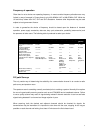
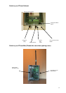
Connections for the Universal & Plastic Housed Global Modem
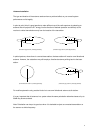
Note with RS422 & RS485 connections it is the rosponsibility of the system builder to ensure that the
connections are correctly terminated. Normally cables with an impedance > 100 Ohms should be used
and terminating resistors (120R bwtween A-B and Z-Y) may aslo be required.
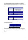
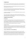
CONFIGURATION:-
Depending upon the model of the modem you will be able to select one of the communication
configurations listed below:-
VHF :
MPT1328
RTcom-Outback
UHF:
MPT1329
RTcom-Outback
VHF/UHF
RTcom-Max
UHF: MPT1329
RTcom-Global
1200-2400bps 1200-4800bps 2400 fixed 2400-9600bps
7 & 8 bit ASCII 7 & 8 bit ASCII 7 & 8 bit ASCII 7 & 8 bit ASCII
Even & odd parity Even & odd parity Even & odd
Parity
Even & odd parity
1 or 2 Stop bits 1 or 2 stop bits 1 or 2 stop bits 1 or 2 stop bits
Operating Modes available with the Global, Max and Outback Modems