


6
3.2.2 CLOSE TO EMERGENCY SOURCE SIDE
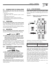
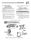
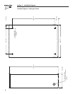
Before proceeding, verify the position of the switch
by observing window “B” in Figure 3.1. If window
“B” reads “ON”, the contacts are closed in the
EMERGENCY (STANDBY) position. No further action
is required. If it reads “OFF”, proceed with Step 1.
Step 1: With the handle attached to the actuating
shaft, move the handle in the direction of the
arrow on the switch cover until it stops - DO
NOT FORCE. Release handle slowly to allow
the spring in the switch box to relax. “OFF”
now appears in Window “A” and “ON” appears
in Window “B”.
3.2.3 RETURN TO NORMAL SOURCE SIDE
Manually actuate switch to return Window “A” to the
“ON” position.
3.3 VOLTAGE CHECKS
3.3.1 UTILITY VOLTAGE CHECKS
1. Turn ON the UTILITY power supply to the trans-
fer switch with whatever means provided (such as
the UTILITY maim line circuit breaker).
DANGER
PROCEED WITH CAUTION. THE TRANSFER
SWITCH IS NOW ELECTRICALLY HOT. CONTACT
WITH LIVE TERMINALS RESULTS IN EXTREMELY
HAZARDOUS AND POSSIBLY FATAL ELECTRICAL
SHOCK.
2. With an accurate AC voltmeter, check for correct
voltage.
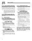
Single-phase utility supply:
Measure across ATS terminal lugs N1 and N2; N1
to NEUTRAL and N2 to NEUTRAL.
DANGER
FAILURE TO TURN OFF THE UTILITY SUPPLY
BEFORE WORKING ON THE UTILITY CONNEC-
TIONS OF THE ATS WILL RESULT IN EXTREMELY
DANGEROUS AND POSSIBLY FATAL ELECTRICAL
SHOCK.
5. When certain that UTILITY supply voltage is cor-
rect and compatible with transfer switch ratings,
turn OFF the UTILITY supply to the transfer
switch.
3.3.2 GENERATOR VOLTAGE CHECKS
1. On the generator panel, set the AUTO/OFF/
MANUAL switch to MANUAL position. The gen-
erator should crank and start.
2. Let the generator stabilize and warm up at no-
load for at least five minutes.
3. Set the generator's main circuit breaker (CB1) to
its ON or CLOSED position.
DANGER
PROCEED WITH CAUTION. GENERATOR
OUTPUT VOLTAGE IS NOW BEING DELIVERED
TO TRANSFER SWITCH TERMINALS. CONTACT
WITH LIVE TERMINALS RESULTS IN EXTREMELY
DANGEROUS AND POSSIBLY FATAL ELECTRICAL
SHOCK.
4. With an accurate AC voltmeter and frequency
meter, check the no-load, voltage and frequency.
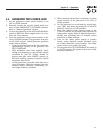
Single-phase generator supply:
Measure across ATS terminal lugs E1 to E2; E1
to NEUTRAL and E2 to NEUTRAL.
a. Frequency .......................................60-62 Hz
b. Terminals E1 to E2 ........................240-246 VAC
c. Terminals E1 to NEUTRAL .............120-123 VAC
d. Terminals E2 to NEUTRAL .............120-123 VAC
5. When certain that UTILITY supply voltage is cor-
rect and compatible with transfer switch ratings,
turn OFF the UTILITY supply to the transfer
switch.
6. Set the generator’s main circuit breaker (CB1) to
its OFF or OPEN position.
7. Set the AUTO/OFF/MANUAL switch to the OFF
position to shut down the generator.
NOTE:
Do NOT proceed until generator AC output volt-
age and frequency are correct and within stated
limits. If the no-load voltage is correct but no-
load frequency is incorrect, the engine governed
speed probably requires adjustment. If no-load
frequency is correct but voltage is not, the voltage
regulator may require adjustment.
Section 3 — Operation
RTS “W” Type Transfer Switch