


4
© 2008 RuggedCom Inc. All rights reserved Rev105
1 Table of Figures
Figure 1: Ethernet panel LED description........................................................................................ 7
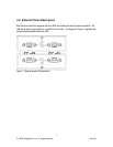
Figure 2: 1000BaseX LC connector ................................................................................................ 8
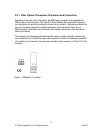
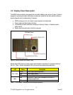
Figure 3: M2000 Series LED Display Panel.................................................................................... 9
Figure 4: M2200 Panel Mounting Diagram.....................................................................................11
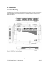
Figure 5: M2000 Series Philips Screw Terminal Block....................................................................12
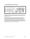
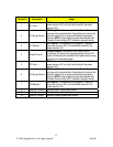
Figure 6: AC Power supply wiring examples...................................................................................14
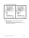
Figure 7: DC Power supply wiring examples..................................................................................15
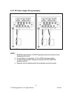
Figure 8: DC And AC power supply wiring examples.....................................................................16
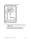
Figure 9: Dielectric Strength (HIPOT) Testing.................................................................................17
Figure 10: Failsafe Alarm Relay Wiring...........................................................................................18
Figure 11: Console port location on display board .........................................................................19
Figure 12: M2200 Console cable ...................................................................................................19
Figure 13: Micro-D port pin configuration........................................................................................20
Figure 14: Mechanical Dimensions .................................................................................................28
2 Table of Tables
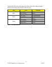
Table 1: LED Display – Device status LED behavior definition....................................................... 9
Table 2: LED Display Description...................................................................................................10
Table 3: M2200 Power terminal block connection description.........................................................13
Table 4: RS232 over RJ45 console cable pin-out ..........................................................................19
Table 5: Cabling categories and 1000BaseTx compliance defined................................................22