


2. Installation
RuggedCom® RuggedPower™ 11 RP100 Installation Guide Rev100
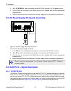
2.4.2. RuggedMAX Power Port / IEEE802.3at Port
The RuggedMax Power port takes data received on the 10/100 Base TX port and injects power
on pins 4, 5 and 7, 8. CAT-5E STP (shielded twisted pair) cable should be used to connect this
port to the powered device. For RP100 units with the “AT” IEEE802.3at-compliance option, the
unit only delivers power when an IEEE802.3at-compliant powered device is attached.
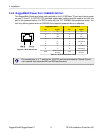
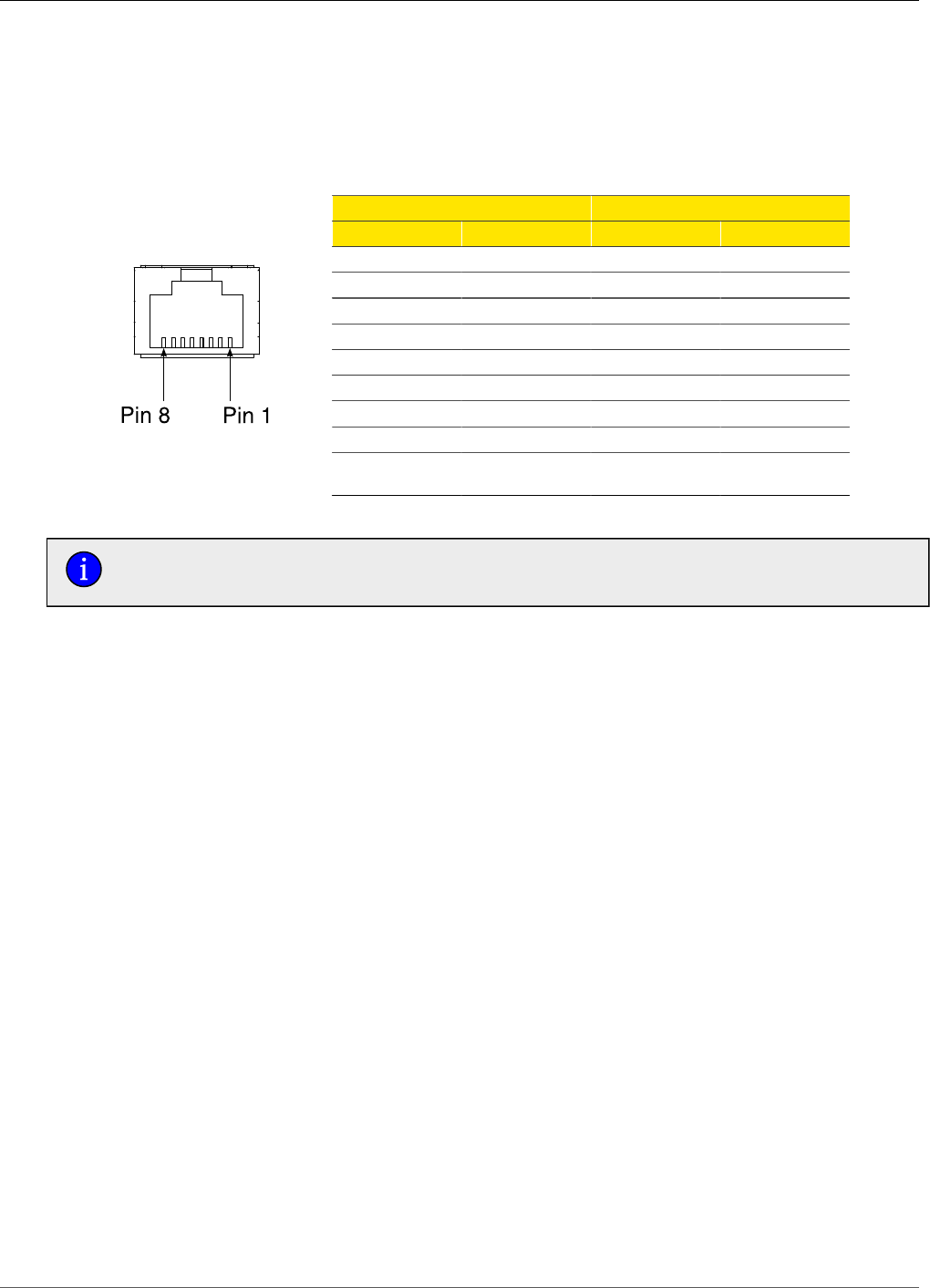
Figure 2.4. RJ45 Port Pinout
RuggedMax Power 10/100 Base Tx
Pin Signal Pin Signal
1 +Tx 1 +Tx
2 -Tx 2 -Tx
3 +Rx 3 +Rx
4 V+ 4 Terminated
5 V+ 5 Terminated
6 -Rx 6 -Rx
7 V- 7 Terminated
8 V- 8 Terminated
Case
Shield (Chassis
Ground)
Case
Shield (Chassis
Ground)
Table 2.1. RJ45 Ethernet Port Pinout
The unused pins, 4, 5, 7, and 8 of the 10/100Tx port are terminated to Chassis Ground
via a network that improves EMI and ESD performance.