


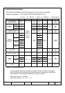
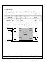
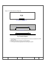
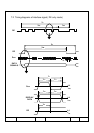
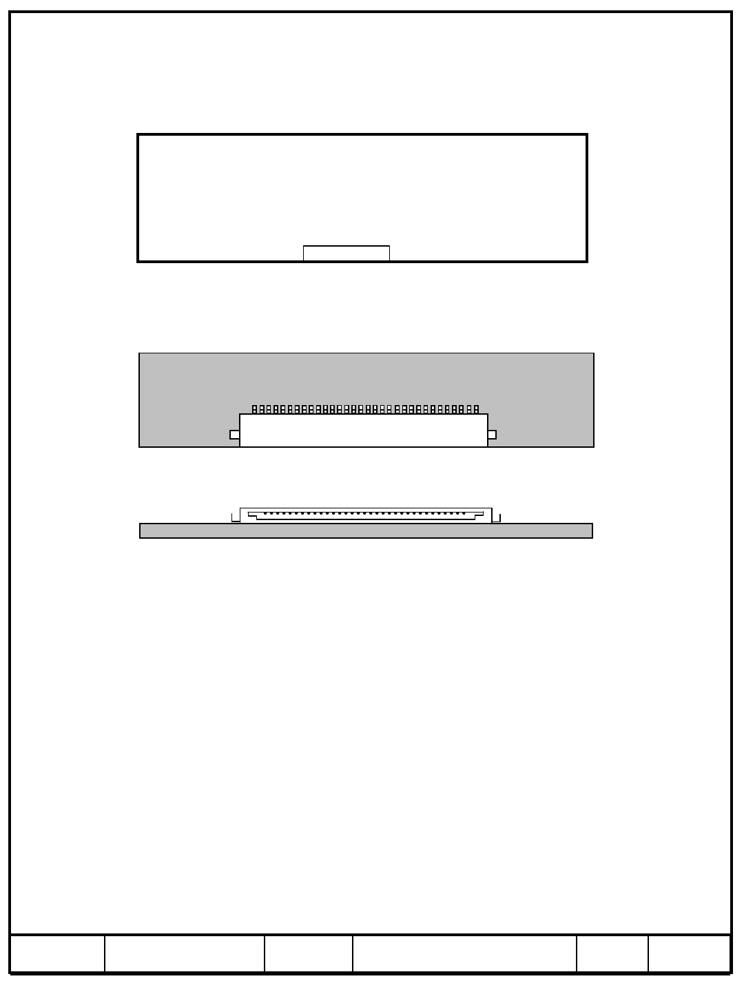
Note(1) Pin number starts from Right side
Pin No. 1 Pin No. 30
PCB
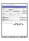
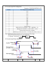
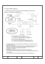
a. All GND pins should be connected together and also be connected to the LCD’s
metal chassis.
b. All power input pins should be connected together.
c. All NC pins should be separated from other signal or power.
Fig. Connector diagram
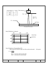
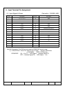
#1
connect name
#30
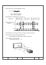
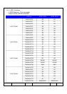
#1
#30