


LENS REPLACEMENT AND INSTALLATION PROCEDURE
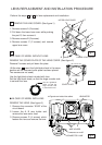
Remove screws A (2 screws).
Pull down the lower lens cover while pushing
the part D, then remove it.
Remove screws B (2 screws).
Remove screws C (2 screws) and remove
upper lens cover.
1
4
Perform the steps to for lens replacement and installation.
1
1.
2.
A
Fig-1
Fig-2
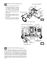
● IN CASE OF MODEL WITHOUT LENS
Remove 2 screws and pull down the plate.
2
3.
4.
UPPER LENS COVER
LOWER LENS COVER
C
B
D
D
COVER PLATE
REMOVE THE LENS COVER. (See figure-1)
(At the step , insert the light-block sheet in the same
position as the removed cover plate has been placed.
Two screws are not used.)
Use the light-block sheet included with lens.
Set the light-block sheet, so that the large rounder side
is set over the lens.
4
REMOVE THE COVER PLATE OF THE LENS COVER. (See figure-2)
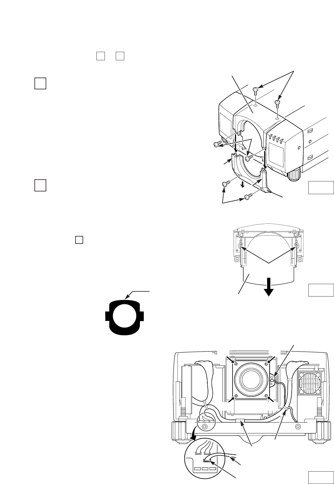
LENS MOTOR LEAD
CONNECTOR “ K16B”
(D)
(D)
(D)
(D)
B
LENS MOTOR
Fig-3
❋ Figure shown inside of the cabinet.
REMOVE THE LENS. (See figure-3.)
1. Remove the connector “K16B” of the
circuit board.
2. Loosen the A, B wire holder and
remove the lens motor lead.
3. Remove screws D (4 screws) which
fastens the lens and remove the lens.
● IN CASE OF MODEL WITH LENS
A
Set the light-block
sheet, so that the
large rounder side
is set over the lens.
SCREWS
WIRE HOLDER