


< previous | home | next >
EZ Manual: M-8400RVe 3
Barcode SATO International Pte Ltd
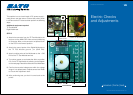
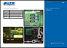
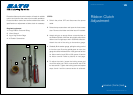
Electric Checks and Adjustments
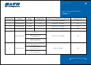
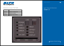
Chart 1
Dial test point Comment Voltage Voltage Range Check pin on TP Test Module and Main PCB Adjustment to VR
0 DC power Supply +5.0 VDC +4.8V to +5.2V CH3A(+5.0V) - CH1A(GND) N/A
1 DC power Supply +2.0 VDC +1.9V to +2.1V CH4A(+2.0V) - CH1A(GND) N/A
2 DC power Supply +3.3 VDC +3.1V to +3.5V CH5A(+3.3V) - CH1A(GND) N/A
3 DC power Supply +24.0 VDC +23.5V to +24.5V CH6A(+24.0V) - CH1A(GND) N/A
4 I-Mark Sensor Level CH1B(+8.4V) - CH1A(GND) VR5
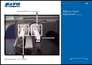
5 Gap sensor Level CH2B - CH1A(GND) VR4
Low level (Set the blank area
on the sensor) = A
High level (Set the I-mark
on the sensor) = B
High level - Low level =
A - B = more than +0.9V
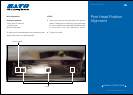
Low level (Set the label backing liner or the
centre hole [in case of the centre hole tag]
on the sensor) = C
High level (Set the label or
tag on the sensor) = D
High level - Low level =
C - D = more than +1.0V