


5
3. Assembly, startup procedure and
dismantling
3.1 UNPACKING, CHECKING
- Check whether the package was delivered
complete (see scope of delivery).
- Check the individual parts for transport
damage.
Warning
Use only undamaged parts!
3.2 ASSEMBLY
The equipment is delivered in a ready-to-operate
condition. The following procedure is appropriate
for assembly:
- Check whether the switch factory-setting is
suitable for your requirements.
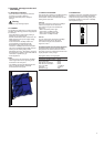
- Pull the terminal block off the Transceiver 100
Mbps TX/FX and wire up the supply voltage
and indicator lines.
- Fit the Transceiver 100 Mbps TX/FX on a
35 mm ISO/DIN rail to DIN EN 50 022.
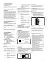
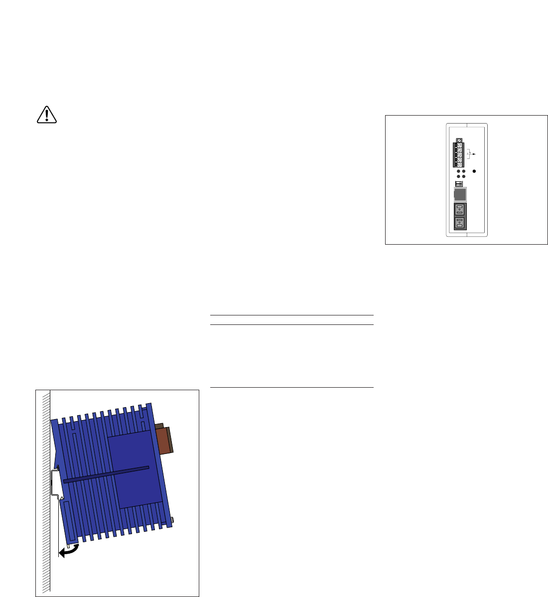
- Suspend the upper snap-in hook of the
Transceiver 100 Mbps TX/FX in the ISO/DIN
rail, insert a screwdriver horizontally under the
housing into the locking slide pull this
downwards (see Fig. 6, dismantling) and press
the bottom of the module onto the ISO/ DIN rail
until it locks in position (Fig. 5).
- Fit the signal lines.
Notes:
- The front panel of the Transceiver 100 Mbps
TX/FX is grounded via the separate ground
connection in the front panel.
- The shielding ground of the twisted pair lines
which can be connected is electrically
connected to the front panel.
3.3 STARTUP PROCEDURE
You start up the Transceiver 100 Mbps TX/FX by
connecting the supply voltage via the 5-pin
terminal block. Lock the terminal block with the
locking screw at the side.
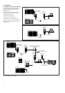
F/O-Line
For a F/O segment the Transceiver 100 Mbps
TX/FX has one port with an SC socket.
The maximum length of an attached F/O
segment is:
- 3000 m at 50/125 µm fiber type
(Transceiver 100 Mbps TX/FX),
- 3000 m at 62.5/125 µm fiber type
(Transceiver 100 Mbps TX/FX).
TP-Line
For a TP segment the Transceiver 100 Mbps
TX/FX has one port with an TP socket.
The maximum length of an attached TP
segment is 100 m.
Propagation delay with half duplex segments
Using half duplex segments the propagation
delay between the terminal devices is 512 bit
times (BT) maximum. Add all components of the
signal path plus a safety margin.
Propagation delay in the signal path:
Components Delay
Transceiver 100 Mbps TX/FX 84 BT
Class II Repeater 92 BT
DTE with TP connection 50 BT
DTE with F/O connection 50 BT
Cat. 5 TP cable 1.112 BT/m
F/O cable 1.0 BT/m
Security margin 4 BT
Fig. 6: Dismantling
Fig. 5: Assembling Transceiver 10 Mbps FX/FX
3.4 DISMANTLING
To take the Transceiver 100 Mbps TX/FX off the
ISO/DIN rail, insert a screwdriver horizontally
under the housing into the locking slide, pull it
downwards and tilt the Transceiver 100 Mbps
TX/FX upwards (Fig. 6).