


1
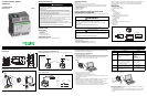
ConneXium Ethernet Gateway
TSXETG100
Installation Guide
63230-319-221A1 10/2009
SAFETY PRECAUTIONS
INTRODUCTION
Box Contents
• ETG unit and connectors
• Registration card
• Installation guide
• Technical Library CD-ROM
• Technical support contact sheet
Additional Resources
Documentation and Firmware: Go to www.schneider-electric.com.
Quick Start Checklist
❏ Mount the unit.
❏ Determine the control power method and connect the power.
❏ Configure the Ethernet communications settings with a web browser (using an Ethernet crossover
cable) or with HyperTerminal (using a null modem cable, which is included in the TCSEAK0100
configuration kit [sold separately]).
❏ Configure the serial ports.
❏ Configure the device list.
❏ Wire the serial ports.
CLASS I, DIVISION 2 COMPLIANT INSTALLATION
REQUIREMENTS AND WARNINGS
This equipment is suitable for use in Class I, Division 2, Groups A, B, C, and D or non-hazardous locations
only.
All terminal strip screws must be tightened to a torque of 5-7 in/lb (0.56 - 0.79 Nm)
Sealed Relay Device information includes:
• Sealed Device: Relay
• Manufacture of Plastic Material: Ticona
• Designation of Plastic Material: H140, E130I, T840 or T130
• Generic Name of Plastic Material: Liquid Crystal Polymer (LCP)
It is recommended that the sealed relay device be inspected periodically to check for degradation of the
materials and to replace the complete product, not the sealed deivce if any degradation is found.
Field conductors need to be suitable for use in a 70°C temperature ambient and “USE COPPER
CONDUCTOR ONLY”.
DESCRIPTION
1. 24 Vdc control power connection
2. 10/100BaseTx (802.3af) connection
3. LEDs:
Ethernet:
• LK: Active link
• TX: Transmitting data
• RX: Receiving data
• 100: Link speed. 100 Mb = ON, 10 Mb = OFF
Serial:
• RS485: RS485 mode = ON, RS232 mode = OFF
• TX: Transmitting data
• RX: Receiving data
Power/Status
4. DIN rail release
5. Reset button (press to reboot the ETG; no data is lost)
6. RS485 connection
7. Dip switches
8. RS232 connection
DANGER
HAZARD OF ELECTRIC SHOCK, EXPLOSION, OR ARC FLASH
• Only qualified workers should install this equipment. Such work should be performed only after
reading this entire set of instructions.
• NEVER work alone.
• Before performing visual inspections, tests, or maintenance on this equipment, disconnect all
sources of electric power. Assume that all circuits are live until they have been completely de-
energized, tested, and tagged. Pay particular attention to the design of the power system. Consider
all sources of power, including the possibility of backfeeding.
• Be sure to follow instructions for Class I, Division 2 environment. Refer to the “Class I, Division 2
Compliant Installation Requirements and Warnings” section.
• Apply appropriate personal protective equipment (PPE) and follow safe electrical practices. For
example, in the USA, see NFPA 70E.
• Turn off all power supplying the equipment in which the ETG is to be installed before installing and
wiring the ETG.
• Always use a properly rated voltage sensing device to confirm that power is off.
• Beware of potential hazards, wear personal protective equipment, and carefully inspect the work
area for tools and objects that may have been left inside the equipment.
• The successful operation of this equipment depends upon proper handling, installation, and
operation. Neglecting fundamental installation requirements may lead to personal injury as well as
damage to electrical equipment or other property.
Failure to follow these instructions will result in death or serious injury.
WARNING
EXPLOSION HAZARD
• Substitution of any components can impair suitabiity for Class I, Division 2.
• Do not disconnect while the circuit is live or unless the area is known to be free of ignitable
concentrations.
Failure to follow this instruction can cause death or serious injury.
WARNING
POTENTIAL EQUIPMENT DAMAGE
Exposure to some solvents can degrade the sealing properties of materials used in this Gateway.
Failure to follow this instruction can cause equipment damage.
1
2
678
3
4
LK
TX
RX
100
RS485
TX
RX
5
/
TOP FRONT BOTTOM
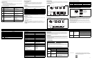
INSTALLATION
Dimensions
DIN Rail Mounting and Removal
Powering the ETG
Power-over-Ethernet (PoE [IEEE 802.3af])
The ETG supports PoE (IEEE 802.3af), allowing the ETG to be powered over an Ethernet connection. Use
either configuration A or B below:
NOTE: Use a PoE injector that fully complies with the IEEE 802.3af standard for active midspan devices,
such as the TCSEAV0100 from Schneider Electric.
24Vdc Control Power
NOTE: For Class I, Division 2 installations, tighten the terminal strip screws to a torque of 5-7 in/lb
(0.56 - 0.79 Nm).
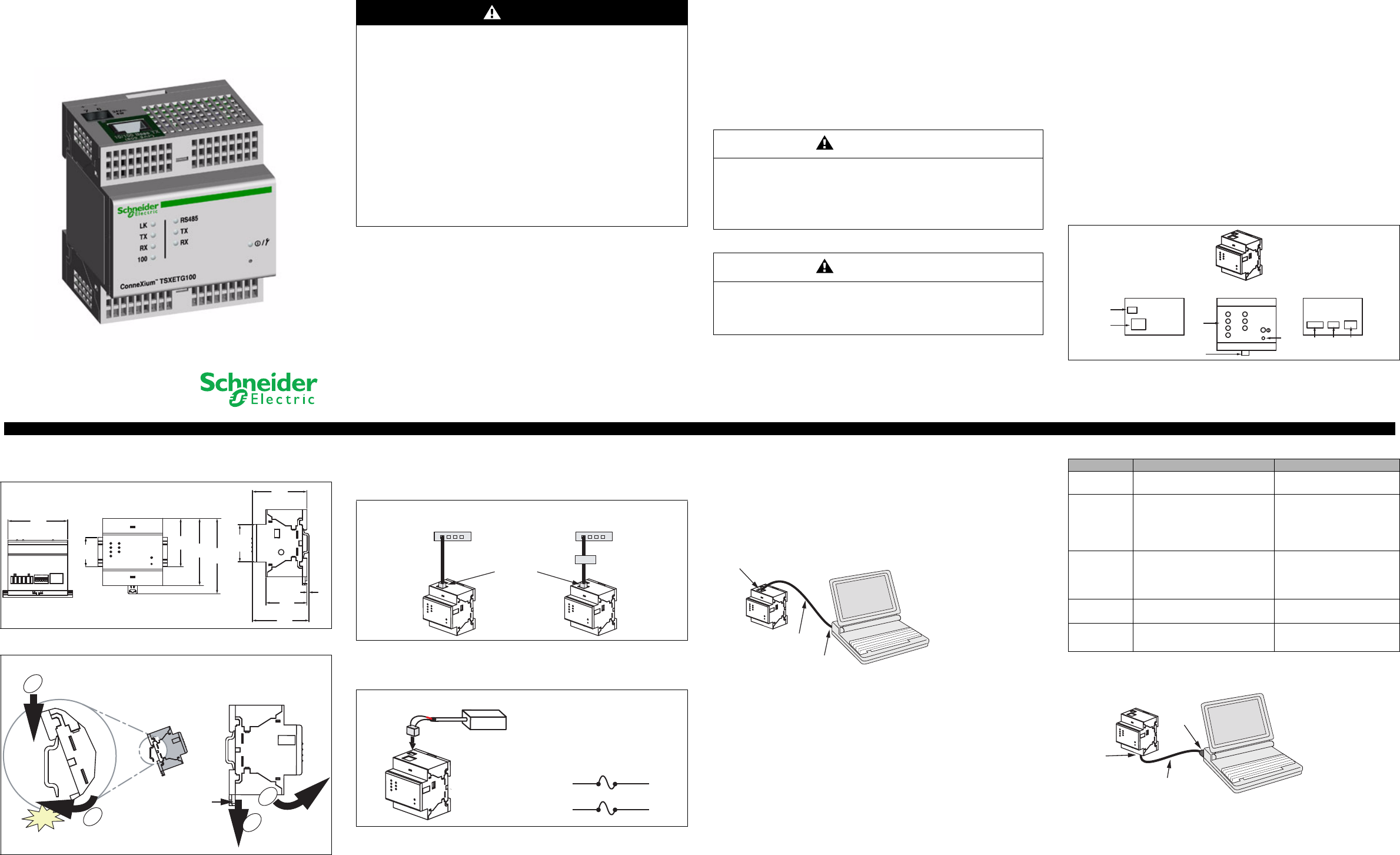
Ethernet Configuration
Before configuring the ETG, obtain a unique static IP address, subnet mask, and default gateway address
from your network administrator. Use a Web browser or HyperTerminal to configure the ETG with the
information obtained from your network administrator.
Ethernet Setup Using a Web Browser
1. Disconnect your computer from your network.
NOTE: After disconnecting from your network, your computer should automatically use the default IP
address 169.254.###.### (### = 0 to 255) and the default subnet mask 255.255.0.0. If the IP address
is not automatically configured, contact your network administrator to set up a static IP address.
2. Connect an Ethernet crossover cable from the ETG to the computer.
NOTE: See “Powering the ETG” for powering options.
3. Start Internet Explorer (version 6.0 or higher).
4. In the Address text box, type 169.254.0.10, then press Enter.
5. Type Administrator for your user name, type Gateway for your password, then click OK. User names
and passwords are case sensitive.
6. Click Setup.
7. If the “Ethernet & TCP/IP” page isn’t open, click Ethernet & TCP/IP in the menu on the left side of the
page.
8. Select the frame format and media type (see Table 1 for a description of each option).
9. Enter your IP address, subnet mask, and default gateway address assigned to your ETG by your
network administrator (see Table 1 for a description of each option), then click Apply.
10.Reconnect your computer to your network. If you assigned a static IP address to your computer in step
1, you must restore your computer’s original settings before reconnecting to your network.
Ethernet Setup Using HyperTerminal
1. Attach a null modem cable (see below).
NOTE: The RJ45 to DB9 adapter and the Ethernet crossover cable are included in the TCSEAK0100
configuration kit (sold separately).
2. Click Start > Run, then type hypertrm.
3. In the Name text box, type a name for the new connection (for example, ETG config), then click OK.
4. In the Connect using drop-down list box, select the computer COM port you will be using, then
click OK.
35
1.38
57.9
2.28
80.8
3.18
90.7
3.57
65.8
2.59
45.2
1.78
2.5
0.10
49.5
1.95
68.3
2.69
72
2.83
Millimeters
Inches
1
2
Click
1
2
DIN Rail
(TS-35)
Slide release
Mount Removal
AB
Midspan PoE Injector
(part number TCSEAV0100)
10/100BaseTx
Ethernet Switch with
endspan PoE ports
Ethernet Switch
+
–
(7) +
(6) –
ETG Control
Power
Connector
Power Supply
+24 Vdc ± 10%
24 Vdc
Power
Source
Fuse
disconnect
Ethernet
crossover
cable
10/100BaseTx
(802.3af) port
To computer
Ethernet port
Table 1: ETG Ethernet and TCP/IP Settings
Option Description Setting
Frame Format
Used to select the format for data sent over
an Ethernet connection.
Ethernet II, 802.3 SNAP
Default: Ethernet II
Media Type
Used to define the physical Ethernet
connection.
• 10T/100Tx Auto
• 10BaseT-HD
• 10BaseT-FD
• 100BaseTX-HD
• 100BaseTX-FD
Default: 10T/100Tx Auto
IP Address
Used to enter the static IP address of the
ETG.
NOTE: If you enter an IP address that is
already in use, you will be prompted to
select a different IP address.
0.0.0.0 to 255.255.255.255
Default: 169.254.0.10
Subnet Mask
Used to enter the Ethernet IP subnet mask
address of your network.
0.0.0.0 to 255.255.255.255
Default: 255.255.0.0
Default Gateway
Used to enter the gateway (router) IP
address used for wide area network (WAN)
communications.
0.0.0.0 to 255.255.255.255
Default: 0.0.0.0
RS232 serial
port
(See Table 3
on page 2
for pinouts)
RJ45 to
DB9
adapter
Ethernet
crossover
cable