


Constellation ES Serial ATA Product Manual, Rev. G 27
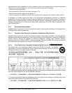
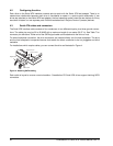
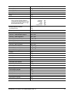
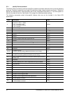
4.4 Drive mounting
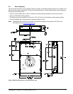
You can mount the drive in any orientation using four screws in the side-mounting holes or four screws in the
bottom-mounting holes. See Figure 5 for drive mounting dimensions. Follow these important mounting precau-
tions when mounting the drive:
• Allow a minimum clearance of 0.030 in (0.76mm) aroun
d the entire perimeter of the drive for cooling.
• Use only 6-32 UNC mounting screws.
• The screws should be inserted no more than 0.150 in (3.81mm) into the bottom or side mounting holes.
• Do not overtighten the mounting screws (maximum torque: 6 in-lb).
Note. These dimensions conform to the Small Form Factor Standards documented in SFF-8301 and
SFF-8323, found at
www.sffcommittee.org
Breather
Hole
mm
in
mm
in
mm
in
Figure 5. Mounting dimensions—top, side and end view