


18
Momentus 5400.2 SATA Removable Drive Cartridge Product Manual, Rev. C
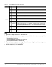
Notes:
1. All pins are in a single row, with a 1.27 mm (0.050”) pitch.
2. The comments on the mating sequence apply to the case of backplane blindmate connector only. In this
case, the mating sequences are:
• the ground pins P4 and P12.
• the pre-charge power pins and the other ground pins.
• the signal pins and the rest of the power pins.
3. There are three power pins for each voltage. One pin from each voltage is used for pre-charge when
installed in a blind-mate backplane configuration.
4. All used voltage pins (V
x
) must be terminated.
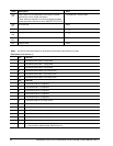
Power
P1 V
33
3.3V power
P2 V
33
3.3V power
P3 V
33
3.3V power, pre-charge, 2nd mate
P4 Ground 1st mate
P5 Ground 2nd mate
P6 Ground 2nd mate
P7 V
5
5V power, pre-charge, 2nd mate
P8 V
5
5V power
P9 V
5
5V power
P10 Ground 2nd mate
P11 Reserved The pin corresponding to P11 in the backplane receptacle connector is also reserved
The corresponding pin to be mated with P11 in the power cable receptacle connector
shall always be grounded
P12 Ground 1st mate.
P13 V
12
12V power, pre-charge, 2nd mate
P14 V
12
12V power
P15 V
12
12V power
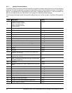
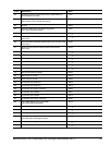
Table 1: Serial ATA connector pin definitions
Segment Pin Function Definition