


C/D
Jumper
CS
Master/Standalone
C/D
Slave
C/D
CS
CS
Jumper
Cable Select
Master or Slave
CS
C/D
Jumper
No Jumpers
1
2
3
4
J6
Standard 4-Pin
Power Connector
J2, Pin 1
40-Pin Task File
Interface
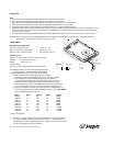
INSTALLATION
Steps:
1. Turn off the computer and all attached peripheral equipment, such as printers and monitors.
2. Remove the screws attaching the computer’s cover, and remove the cover from the system.
3. Remove the drive from the ESD (Electro Static Discharge) bag, carefully placing the drive on your work surface.
4. Configure the disk drive jumpers as necessary. Refer to master/slave jumper table below for more details.
5. Connect the cables; align the colored striped edge of the interface cable to pin 1 of the drive interface connector.
6. Partially insert the drive into the drive bay. Select an unused power connector from the power supply and connect it to the drive. If there are no unused
power connections on the power supply, you can purchase a “Y” cable adapter from your dealer. This connector will allow you to add another power
connection for your new drive.
7. Now that the drives are jumpered, connected, and have power cables attached, secure the drive or the mounting frame with four 6-32x.25 screws.
CAUTION: Do not use screws of excess length when attaching the drive. Damage to the drive’s circuit board could result. The maximum insertion in
bottom holes is .25”, the maximum insertion for side holes is .125”.
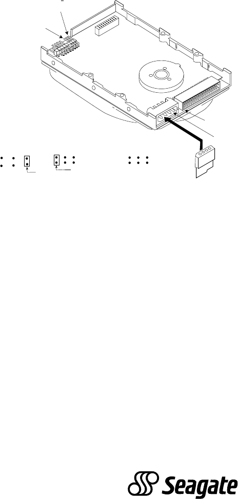
JUMPER TABLES
Master/Slave (C/D) Jumper Table
Only drive in single drive system* = Jumper pins 1 & 2
Master (C:) drive in a dual drive system* = Jumper pins 1 & 2
Slave (D:) drive in a dual drive system = Remove jumper pins 1 & 2
Cable Select (CS)
(Refer to your system owner's manual for use of this function)
Disabled* = Remove jumper pins 5 & 6
Enabled = Jumper pins 5 & 6
* Default setting
Note: Pins 3, 4 and 7-18 are reserved and should not be used
8. All Seagate ATA disk drives are low level formatted at the factory.
It is only necessary to run SETUP, FDISK and DOS FORMAT.
9. AT BIOS (CMOS) setup ( refer to your system owners manual):
a) Many newer computers will automatically install your Seagate
disk drive. Insure that your Master/Slave (C/D) jumper is properly configured.
b) If the AT BIOS supports a user definable drive type, program the BIOS
to the parameters in the table below.
NOTE: Precomp should be set to zero (0)
for all drives and the Landing Zone should be set to the number of cylinders
.
c) If the AT BIOS does not support user definable drive type select a drive type that is
close to the drives parameters, but do not exceed the drives formatted capacity.
d) You may use the EZ-Drive
®
installation utility supplied with your Seagate disk drive
to do the configuration. Insert the EZ-Drive diskette into drive A:> and type EZ <ENTER>
and it will automatically configure the drive.
Model Heads Cylinders Sectors Capacity *
CFS270A 14 600 63 270MB
CFS425A 16 839 62 426MB
ST3541A 14 1198 63 540MB
ST3635A 16 1238 63 638MB
ST3851A 16 1652 63 852MB
ST3851A1 16 1651 63 852MB
ST31081A 16 2097 63 1,082MB
ST31275A 16 2477 63 1,278MB
ST31621A 16 3146 63 1,623MB
* 1MB = 1,000,000 Bytes
10. The drive is now ready for partioning and high-level formatting with the operating system.
If you did not use EZ-Drive (EZ-Drive performs these functions), 1.) partition the drive first
using the FDISK command from MS-DOS version 3.3 or higher and 2.) high-level format the
drive using the FORMAT command from MS-DOS.
EZ-Drive is the registered trademark of Micro House International, Inc.