


18 Momentus Thin Series SATA Product Manual, Rev. B
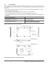
3.4 Drive mounting
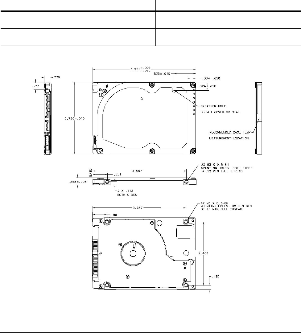
You can mount the drive using four screws in the side-mounting holes or four screws in the bottom-mounting
holes. See Figure 4 for drive mounting dimensions. Follow these important mounting precautions when mount-
ing the drive:
• Allow a minimum clearance of 0.030 in
ches (0.76 mm) around the entire perimeter of the drive for cooling.
• Use only M3 UNC mounting screws.
• Do not overtighten the mounting screws. Maximum torque: 4.0 in-lb (0.4519 N-m).
• Four (4) threads (0.080 inches, 2.032 mm) minimum screw engagement recommended.
• Avoid excessive drive distortion when mounting. Refer to the following specifications for stiffness/deflection
in
formation:
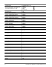
Top cover stiffness/deflection
Operating with no performance degradation, emitted noise,
mechanical damage, or hard errors
10 mm probe: 1.02kgf or
5 mm probe: 0.92kgf
Non-operating with no hard errors 20 mm probe: 2kgf at any point of top cover
20 mm probe: 15kgf at top cover edges only
Measurements shown in Figure 4 are in inches.
Figure 4. Mounting dimensions—top, side and end view