


SEAGATE LAPTOP SSHD SATA PRODUCT MANUAL, REV. D 18
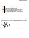
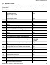
SERIAL ATA (SATA) INTERFACE
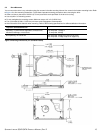
• the signal pins and the rest of the power pins.
3 There are three power pins for each voltage. One pin from each voltage is used for pre-charge when installed in a blind-mate
backplane configuration.
4 All used voltage pins (V
x
) must be terminated.
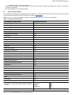
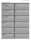
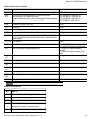
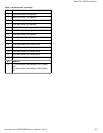
5.3 SUPPORTED ATA COMMANDS
Table 9 lists Serial ATA standard commands that the drive supports. For a detailed description of the ATA commands, refer to the Serial
ATA International Organization: Serial ATA (Revision 2.6). Refer to
www.sata-io.org.
Refer to S.M.A.R.T. commands on page 25 for details and subcommands used in the S.M.A.R.T. implementation.
Table 9 Supported ATA commands
ATA-standard commands names Command code (in hex)
Device Configuration Restore B1h/C0h
Device Configuration Freeze Lock B1h/C1h
Device Configuration Identify B1h/C2h
Device Configuration Set B1h/C3h
Download Microcode 92h
Execute Device Diagnostics 90h
Flush Cache E7h
Flush Cache Extended EAh
Identify Device ECh
Initialize Device Parameters 91h
Read Buffer E4h
Read DMA C8h
Read DMA Extended 25h
Read DMA without Retries C9h
Read Long with Retries 22h
Read Long without Retries 23h
Read Multiple C4h
Read Multiple Extended 29h
Read Native Max Address F8h
Read Native Max Address Extended 27h
Read Sectors 20h
Read Sectors Extended 24h
Read Sectors without Retries 21h
Read Verify Sectors 40h
Read Verify Sectors Extended 42h
Read Verify Sectors without Retries 41h
Seek 70h
Set Features EFh
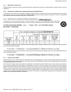
Set Max Address F9h
Note: Individual Set Max commands are identified by the
value placed in the Set Max Features register as defined to
the right.
Address:
Password:
Lock:
Unlock:
Freeze Lock:
00
H
01
H
02
H
03
H
04
H
Set Max Address Ext 37h