


SEAGATE 600 PRO SSD PRODUCT MANUAL, REV. A 22
4.0 SERIAL ATA (SATA) INTERFACE
These drives use the industry-standard Serial ATA interface that supports FIS data transfers. It supports ATA programmed
input/output (PIO) modes 0–4; multiword DMA modes 0–2, and Ultra DMA modes 0–6.
For detailed information about the Serial ATA interface, refer to the “Serial ATA: High Speed Serialized AT Attachment”
specification.
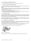
4.1 HOT-PLUG COMPATIBILITY
Seagate 600 Pro SSD drives incorporate connectors which enable you to hot plug these drives in accordance with the Serial
ATA II: Extension to Serial ATA 1.0a specification. This specification can be downloaded from www.serialata.org.
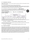
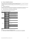
4.2 SERIAL ATA DEVICE PLUG CONNECTOR PIN DEFINITIONS
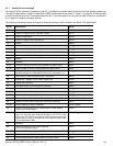
Table 9 summarizes the 2.5” drive Signal and Power SATA Plug.
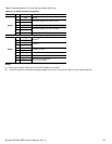
Notes:
[1] Ground pins 4 and 12 mate first on SATA backplane connectors.
[2] The three V
33
pins are unused but connected together on the drive. They can be used for a drive-in-place detection.
[3] The three V
12
pins are unused but connected together on the drive. They can be used for a drive-in-place detection.
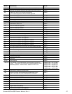
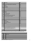
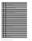
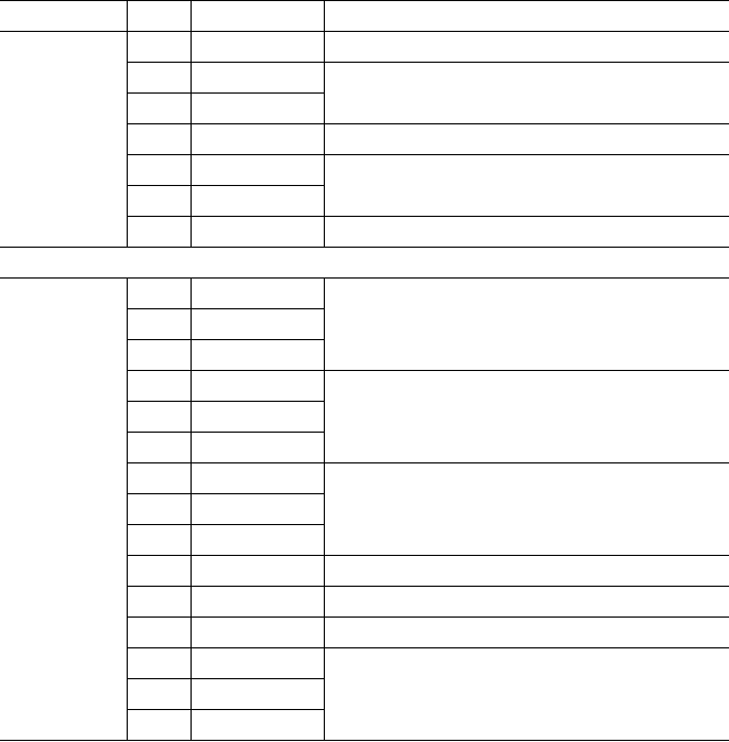
Table 9 2.5” SATA Connector Plug Pinout
Segment Pin Function Definition
Signal
S1 GND Ground
S2 A+
Differential Signal Pair (Host to Drive)
S3 A-
S4 GND Ground
S5 B-
Differential Signal Pair (Drive to Host)
S6 B+
S7 GND Ground
Key and spacing separate signal and power segments
Power
P1 V
33
Unused
[2]
P2 V
33
P3 V
33
P4 GND
Ground
[1]
P5 GND
P6 GND
P7 V
5
5V power to DriveP8 V
5
P9 V
5
P10 Ground Ground
P11 LED Signal Activity LED: Driven low to light
P12 Ground Ground
[1]
P13 V
12
Unused
[3]
P14 V
12
P15 V
12