


Barracuda 180 Product Manual, Rev. A 49
9.5 Synchronous data transfer
9.5.1 Synchronous data transfer periods supported
The data transfer period to be used by the drive and the initiator is established by an exchange of messages
during the Message Phase of operation. See the section on message protocol in the SCSI Interface Product
Manual, part number 75789509. In the following tables, M is the synchronous period value (in the transfer rate
negotiation message) that represents the associated transfer period and transfer rate values.
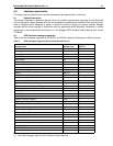
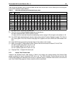
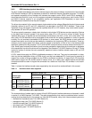
Table 9 lists the synchronous data transfer periods supported by the drive in DT Data phase. DT Data phase is
only allowed when using the LVD interface.
Table 9: Synchronous DT Data transfer periods
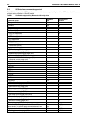
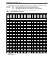
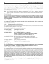
Table 10 lists the synchronous data transfer periods supported by the drive in ST Data phase. ST Data phase
is allowed with either LVD or SE interface except as noted.
Table 10: Synchronous ST Data transfer periods
9.5.2 REQ/ACK offset
Barracuda 180 family drives support REQ/ACK offset values from 7 to 63 (3Fh). Offsets 1 through 6 are nego-
tiated to 0 (asynchronous transfer).
9.6 Physical interface
This section describes the connectors, cables, signals, terminators and bus timing of the DC and SCSI I/O
interface. See Section 9.8 and Section 9.9 for additional terminator information.
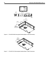
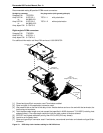
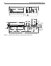
Figures 16 and 17 show the locations of the DC power connector, SCSI interface connector, drive select head-
ers, and option select headers.
Details of the physical, electrical and logical characteristics are given in sections following, while the SCSI
operational aspects of Seagate drive interfaces are given in the SCSI Interface Product Manual.
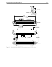
9.6.1 DC cable and connector
ST1181677LW/LWV drives receive DC power through a 4 pin connector (see Figure 18 for pin assignment)
mounted at the rear of the main PCBA. Recommended part numbers of the mating connector are listed below,
but equivalent parts may be used.
LC/LCV model drives receive power through the 80-pin I/O connector. See Tables 14 and 15.
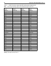
M (decimal)
Transfer period
(nanoseconds)
Transfer rate
(megatransfers/second)
9 12.5 80.0
10 25 40.0
12 50 20.0
25 100 10.0
M (decimal)
Transfer period
(nanoseconds)
Transfer rate
(megatransfers/second)
10 25
40.0
1
1. This transfer rate is only allowed when using the LVD interface.
12 50 20.0
25 100 10.0
50 200 5.0
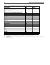
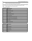
Type of cable Connector Contacts (20-14 AWG)
14 AWG MP 1-480424-0 AMP 60619-4 (Loose Piece)
AMP 61117-4 (Strip)